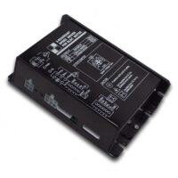

Brief Introduction:
- Surface mounted technology to improve the reliability of the circuit.
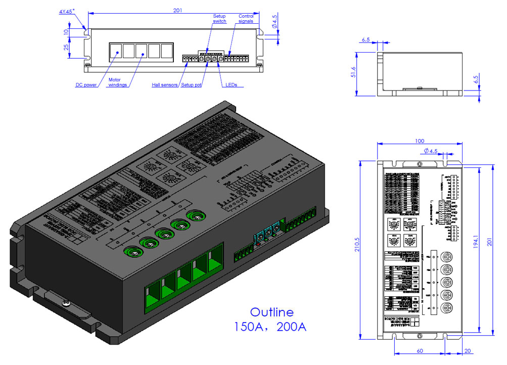
- PLC interface, amazing 200A super high current with low voltage and incredible small dimension.
- We present industrial chips to meet industrial application temperature requirements.
- Optoelectronic isolation for analog voltage / PWM pulse / pulse frequency signal and other security interfaces.
- Super reliable design with safe foreward and reverse, safe start, anti-interference, over temperature / over current / short circuit / under voltage / over voltage and other protections.
Definition of Part number:
BLSD | 24 | 35 | WDC | 2Q | H | F | P | T |
BLDC drive | Rated Voltage | Peak current limit | DC input ① | Control mode | Parameter ② | PG type ③ | Speed regulation type ④ | Temp ⑤ |
① : This code shows the DC Power input type of the drive: WDC = Wide range DC input; LDC = Ultra low voltage DC input; DC = Normal DC input; AC = AC input; ADC = AC and DC dual purpose.
② : This code shows the parameter type of the drive: H = High current; N = Variable parameter; S = Simple fixed parameter; SH = Small type high voltage; HV = High voltage.
③ : This code shows the PG type: F = PG 1x hall sensor signal/phase, None= 6 x hall sensor signal/phase.
④ : This code shows the speed regulation type: P = 0-3KHz speed regulation, None = voltage command.
⑤ : This code shows the temperature range of the drive: T = -40 ~ +65 ℃ , None = -10 ~ +45℃ .
Note: In order to let the part number easier to read, Some part number code will not be shown in the specification table, a code “X” will be instead. The full part number will be provided in the quotation or the proforma invoice…
Specifications:
| Model | Temperature range (ºC) | Voltage range (VDC) | I-pk (A) | I-con (A) | 60º/120º Hall sensor | PWM f(kHz) | PI Close loop of speed | SV Ramp time (S) | SV Range (V) | LV /OV | Alm | PG | PI Close loop of current | Para-meter Settings By Switch And Pot | SC /OT | Safe F/R | Safe Start | Heat Sink |
|---|---|---|---|---|---|---|---|---|---|---|---|---|---|---|---|---|---|---|
| BLSD2435DC-2Q-H-X | -10~+45 -40~+65 | 17~32 | 17.5~35 | 8.75~17.5 | √ | 15 | √ | 0.1~10 | 0~5 | √ | √ | 24p@8-pole | √ | √ | √ | √ | √ | √ |
| BLSD2450DC-2Q-H-X | -10~+45 -40~+65 | 17~32 | 25~50 | 12.5~25 | √ | 15 | √ | 0.1~10 | 0~5 | √ | √ | 24p@8-pole | √ | √ | √ | √ | √ | √ |
| BLSD2475DC-2Q-H-X | -10~+45 -40~+65 | 17~32 | 37.5~75 | 18.75~37.5 | √ | 15 | √ | 0.1~10 | 0~5 | √ | √ | 24p@8-pole | √ | √ | √ | √ | √ | √ |
| BLSD24100DC-2Q-H-X | -10~+45 -40~+65 | 17~32 | 50~100 | 25~50 | √ | 15 | √ | 0.1~10 | 0~5 | √ | √ | 24p@8-pole | √ | √ | √ | √ | √ | √ |
| BLSD24150DC-2Q-H-X | -10~+45 -40~+65 | 17~32 | 150 | 75 | √ | 15 | √ | 0.1~10 | 0~5 | √ | √ | 24p@8-pole | √ | √ | √ | √ | √ | √ |
| BLSD24200DC-2Q-H-X | -10~+45 -40~+65 | 17~32 | 200 | 100 | √ | 15 | √ | 0.1~10 | 0~5 | √ | √ | 24p@8-pole | √ | √ | √ | √ | √ | √ |
| BLSD3635DC-2Q-H-X | -10~+45 -40~+65 | 27~45 | 17.5~35 | 8.75~17.5 | √ | 15 | √ | 0.1~10 | 0~5 | √ | √ | 24p@8-pole | √ | √ | √ | √ | √ | √ |
| BLSD3650DC-2Q-H-X | -10~+45 -40~+65 | 27~45 | 25~50 | 12.5~25 | √ | 15 | √ | 0.1~10 | 0~5 | √ | √ | 24p@8-pole | √ | √ | √ | √ | √ | √ |
| BLSD3675DC-2Q-H-X | -10~+45 -40~+65 | 27~45 | 37.5~75 | 18.75~37.5 | √ | 15 | √ | 0.1~10 | 0~5 | √ | √ | 24p@8-pole | √ | √ | √ | √ | √ | √ |
| BLSD36100DC-2Q-H-X | -10~+45 -40~+65 | 27~45 | 50~100 | 25~50 | √ | 15 | √ | 0.1~10 | 0~5 | √ | √ | 24p@8-pole | √ | √ | √ | √ | √ | √ |
| BLSD36150DC-2Q-H-X | -10~+45 -40~+65 | 27~45 | 150 | 75 | √ | 15 | √ | 0.1~10 | 0~5 | √ | √ | 24p@8-pole | √ | √ | √ | √ | √ | √ |
| BLSD36200DC-2Q-H-X | -10~+45 -40~+65 | 27~45 | 200 | 100 | √ | 15 | √ | 0.1~10 | 0~5 | √ | √ | 24p@8-pole | √ | √ | √ | √ | √ | √ |
| BLSD4835DC-2Q-H-X | -10~+45 -40~+65 | 37~56 | 17.5~35 | 8.75~17.5 | √ | 15 | √ | 0.1~10 | 0~5 | √ | √ | 24p@8-pole | √ | √ | √ | √ | √ | √ |
| BLSD4850DC-2Q-H-X | -10~+45 -40~+65 | 37~56 | 25~50 | 12.5~25 | √ | 15 | √ | 0.1~10 | 0~5 | √ | √ | 24p@8-pole | √ | √ | √ | √ | √ | √ |
| BLSD4875DC-2Q-H-X | -10~+45 -40~+65 | 37~56 | 37.5~75 | 18.75~37.5 | √ | 15 | √ | 0.1~10 | 0~5 | √ | √ | 24p@8-pole | √ | √ | √ | √ | √ | √ |
| BLSD48100DC-2Q-H-X | -10~+45 -40~+65 | 37~56 | 50~100 | 25~50 | √ | 15 | √ | 0.1~10 | 0~5 | √ | √ | 24p@8-pole | √ | √ | √ | √ | √ | √ |
| BLSD48150DC-2Q-H-X | -10~+45 -40~+65 | 37~56 | 150 | 75 | √ | 15 | √ | 0.1~10 | 0~5 | √ | √ | 24p@8-pole | √ | √ | √ | √ | √ | √ |
| BLSD48200DC-2Q-H-X | -10~+45 -40~+65 | 37~56 | 200 | 100 | √ | 15 | √ | 0.1~10 | 0~5 | √ | √ | 24p@8-pole | √ | √ | √ | √ | √ | √ |
| BLSD1235LDC-2Q-H-X (Ultra Low Voltage) | -10~+45 -40~+65 | 5~18 | 17.5~35 | 8.75~17.5 | √ | 15 | √ | 0.1~10 | 0~5 | √ | √ | 24p@8-pole | √ | √ | √ | √ | √ | √ |
| BLSD1250LDC-2Q-H-X (Ultra Low Voltage) | -10~+45 -40~+65 | 5~18 | 25~50 | 12.5~25 | √ | 15 | √ | 0.1~10 | 0~5 | √ | √ | 24p@8-pole | √ | √ | √ | √ | √ | √ |
| BLSD1275LDC-2Q-H-X (Ultra Low Voltage) | -10~+45 -40~+65 | 5~18 | 37.5~75 | 18.75~37.5 | √ | 15 | √ | 0.1~10 | 0~5 | √ | √ | 24p@8-pole | √ | √ | √ | √ | √ | √ |
| BLSD12100LDC-2Q-H-X (Ultra Low Voltage) | -10~+45 -40~+65 | 5~18 | 50~100 | 25~50 | √ | 15 | √ | 0.1~10 | 0~5 | √ | √ | 24p@8-pole | √ | √ | √ | √ | √ | √ |
| BLSD12150LDC-2Q-H-X (Ultra Low Voltage) | -10~+45 -40~+65 | 5~18 | 150 | 75 | √ | 15 | √ | 0.1~10 | 0~5 | √ | √ | 24p@8-pole | √ | √ | √ | √ | √ | √ |
| BLSD12200LDC-2Q-H-X (Ultra Low Voltage) | -10~+45 -40~+65 | 5~18 | 200 | 100 | √ | 15 | √ | 0.1~10 | 0~5 | √ | √ | 24p@8-pole | √ | √ | √ | √ | √ | √ |
| BLSD4835WDC-2Q-H-X (Ultra Wide Voltage Range) | -10~+45 -40~+65 | 17~56 | 17.5~35 | 8.75~17.5 | √ | 15 | √ | 0.1~10 | 0~5 | √ | √ | 24p@8-pole | √ | √ | √ | √ | √ | √ |
| BLSD4850WDC-2Q-H-X (Ultra Wide Voltage Range) | -10~+45 -40~+65 | 17~56 | 25~50 | 12.5~25 | √ | 15 | √ | 0.1~10 | 0~5 | √ | √ | 24p@8-pole | √ | √ | √ | √ | √ | √ |
| BLSD4875WDC-2Q-H-X (Ultra Wide Voltage Range) | -10~+45 -40~+65 | 17~56 | 37.5~75 | 18.75~37.5 | √ | 15 | √ | 0.1~10 | 0~5 | √ | √ | 24p@8-pole | √ | √ | √ | √ | √ | √ |
| BLSD48100WDC-2Q-H-X (Ultra Wide Voltage Range) | -10~+45 -40~+65 | 17~56 | 50~100 | 25~50 | √ | 15 | √ | 0.1~10 | 0~5 | √ | √ | 24p@8-pole | √ | √ | √ | √ | √ | √ |
| BLSD48150WDC-2Q-H-X (Ultra Wide Voltage Range) | -10~+45 -40~+65 | 17~56 | 150 | 75 | √ | 15 | √ | 0~5 | 0~5 | √ | √ | 24p@8-pole | √ | √ | √ | √ | √ | √ |
| BLSD48200WDC-2Q-H-X (Ultra Wide Voltage Range) | -10~+45 -40~+65 | 17~56 | 200 | 100 | √ | 15 | √ | 0~5 | 0~5 | √ | √ | 24p@8-pole | √ | √ | √ | √ | √ | √ |
Technical Note:
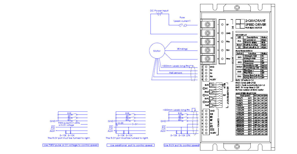
1.Control signals:
F/R—–H or Open=Forward, L or Close=Reverse
EN——H or Open=Disable, L or Close=Enable
BK——H or Open=Running, L or Close=Brake
SV——0~5V speed reference(112K input resistance)
PG—–Speed pulse output(OC)
ALM—Alarm output(OC)
2. Signal wire:
Control signal cable and hall sensors cable can not be tied together with windings cable, otherwise, it will take interference. The long wire should be shielded wire.
3. Alarm conditions:
a. Hall sensor signals are not correct.
b. LV or OV for 1~3S.
c. Short circuit and Over temperature of case (80℃)..
d. Over load for 5~6s continuously.
e. It can be reset by Turn-Off-On DC Power or Disable the driver once.
4. LED indicator:
SC——–Bright=Short circuit , Dark=driver is OK
P/A——-Bright=Driver is OK, Blink=Driver is in alarm
SHAFT—-Bright=Motor shaft is moving, Dark=Motor shaft is in static
5. Braking operation:
The motor speed must be less than the safe brake speed Ns when you brake the motor.
For Y windings, Ns=√3 x Ip x RL x N/ (2x Vp)
For △windings, Ns=IP x RL x N/ (2 x √3 x Vp)
Ip=Peak current(A), RL=Line to line resistance of windings(Ohm)
N=No-load speed(rpm), Vp=Rated voltage(V), Ns=Safe brake speed(rpm)
6. Safe F/R:
If you change F/R of the driver rapidly, it will stop the power stage and motor will be free until the speed is detected as zero,and then to drive in correct direction. This means smooth reverse.
7. Safe start:
If the motor speed is not detected as zero at power on, the driver will be free until the motor speed is zero.
8. Drive setup by pot and switch:
R-SV pot=SV voltage ratio, R-LG pot=Loop gain, R-PC=Peak current ratio, R-RT pot=Ramp time
SW1=60/120 Hall sensors, SW2=Open/Close loop, SW3,4=Speed/Current loop, SW5=Loop filter time, SW6=SV ramp time setting, SW7,8,9,10=Speed range setting.
9. Peak current selection:
Ip>=2xIr or Ip>=4xPo/Vp, Ip is peak current of driver(A), Ir is rated current of motor(A)
Po is rated output power of motor(W), Vp is rated voltage of driver(V)
Customization:
 |  |  |
| Heat sink | Motor tuning | Logo / brandmark |
- Heat Sink: Heat sink can be added according to customer request.
- Motor Tuning: Drivers can be tuned to fit the motors with different poles to match customer’s applications.
- Logo and brandmark: Customer’s Logo/brandmark can be printed on the frame of the driver according to the customer’s request.