
Brief Introduction
- Surface mounted technology to improve the reliability of the circuit.
- PLC interface, amazing 200A super high current with low voltage and incredible small dimension.
- We present industrial chips to meet industrial application temperature requirements.
- Optoelectronic isolation for analog voltage / PWM pulse / pulse frequency signal and other security interfaces.
- Super reliable design with safe foreward and reverse, safe start, anti-interference, over temperature / over current / short circuit / under voltage / over voltage and other protections.
Definition of Part number
| BLSD | 24 | 35 | WDC | 2Q | H | F | P | T |
|---|---|---|---|---|---|---|---|---|
| BLDC drive | Rated Voltage | Peak current limit | DC input ① | Control mode | Parameter ② | PG type ③ | Speed regulation type ④ | Temp ⑤ |
- ① DC input: This code shows the DC Power input type of the drive: WDC = Wide range DC input; LDC = Ultra low voltage DC input; DC = Normal DC input; AC = AC input; ADC = AC and DC dual purpose.
- ② Parameter: This code shows the parameter type of the drive: H = High current; N = Variable parameter; S = Simple fixed parameter; SH = Small type high voltage; HV = High voltage.
- ③ PG type: This code shows the PG type: F = PG 1x hall sensor signal/phase, None= 6 x hall sensor signal/phase.
- ④ Speed regulation type: This code shows the speed regulation type: P = 0-3KHz speed regulation, None = voltage command.
- ⑤ Temp: This code shows the temperature range of the drive: T = -40 ~ +65 ℃ , None = -10 ~ +45℃ .
Note: In order to let the part number easier to read, Some part number code will not be shown in the specification table, a code “X” will be instead. The full part number will be provided in the quotation or the proforma invoice…
Specifications
| Model | Temperature range (ºC) | Voltage range (VDC) | I-pk (A) | I-con (A) | 60º/120º Hall sensor | PWM f(kHz) | PI Close loop of speed | SV Ramp time (S) | SV Range (V) | LV /OV | Alm | PG | PI Close loop of current | Para-meter Settings By Switch And Pot | SC /OT | Safe F/R | Safe Start | Heat Sink |
|---|---|---|---|---|---|---|---|---|---|---|---|---|---|---|---|---|---|---|
| BLSD2435DC-2Q-H-X | -10~+45 -40~+65 | 17~32 | 17.5~35 | 8.75~17.5 | √ | 15 | √ | 0.1~10 | 0~5 | √ | √ | 24p@8-pole | √ | √ | √ | √ | √ | √ |
| BLSD2450DC-2Q-H-X | -10~+45 -40~+65 | 17~32 | 25~50 | 12.5~25 | √ | 15 | √ | 0.1~10 | 0~5 | √ | √ | 24p@8-pole | √ | √ | √ | √ | √ | √ |
| BLSD2475DC-2Q-H-X | -10~+45 -40~+65 | 17~32 | 37.5~75 | 18.75~37.5 | √ | 15 | √ | 0.1~10 | 0~5 | √ | √ | 24p@8-pole | √ | √ | √ | √ | √ | √ |
| BLSD24100DC-2Q-H-X | -10~+45 -40~+65 | 17~32 | 50~100 | 25~50 | √ | 15 | √ | 0.1~10 | 0~5 | √ | √ | 24p@8-pole | √ | √ | √ | √ | √ | √ |
| BLSD24150DC-2Q-H-X | -10~+45 -40~+65 | 17~32 | 150 | 75 | √ | 15 | √ | 0.1~10 | 0~5 | √ | √ | 24p@8-pole | √ | √ | √ | √ | √ | √ |
| BLSD24200DC-2Q-H-X | -10~+45 -40~+65 | 17~32 | 200 | 100 | √ | 15 | √ | 0.1~10 | 0~5 | √ | √ | 24p@8-pole | √ | √ | √ | √ | √ | √ |
| BLSD3635DC-2Q-H-X | -10~+45 -40~+65 | 27~45 | 17.5~35 | 8.75~17.5 | √ | 15 | √ | 0.1~10 | 0~5 | √ | √ | 24p@8-pole | √ | √ | √ | √ | √ | √ |
| BLSD3650DC-2Q-H-X | -10~+45 -40~+65 | 27~45 | 25~50 | 12.5~25 | √ | 15 | √ | 0.1~10 | 0~5 | √ | √ | 24p@8-pole | √ | √ | √ | √ | √ | √ |
| BLSD3675DC-2Q-H-X | -10~+45 -40~+65 | 27~45 | 37.5~75 | 18.75~37.5 | √ | 15 | √ | 0.1~10 | 0~5 | √ | √ | 24p@8-pole | √ | √ | √ | √ | √ | √ |
| BLSD36100DC-2Q-H-X | -10~+45 -40~+65 | 27~45 | 50~100 | 25~50 | √ | 15 | √ | 0.1~10 | 0~5 | √ | √ | 24p@8-pole | √ | √ | √ | √ | √ | √ |
| BLSD36150DC-2Q-H-X | -10~+45 -40~+65 | 27~45 | 150 | 75 | √ | 15 | √ | 0.1~10 | 0~5 | √ | √ | 24p@8-pole | √ | √ | √ | √ | √ | √ |
| BLSD36200DC-2Q-H-X | -10~+45 -40~+65 | 27~45 | 200 | 100 | √ | 15 | √ | 0.1~10 | 0~5 | √ | √ | 24p@8-pole | √ | √ | √ | √ | √ | √ |
| BLSD4835DC-2Q-H-X | -10~+45 -40~+65 | 37~56 | 17.5~35 | 8.75~17.5 | √ | 15 | √ | 0.1~10 | 0~5 | √ | √ | 24p@8-pole | √ | √ | √ | √ | √ | √ |
| BLSD4850DC-2Q-H-X | -10~+45 -40~+65 | 37~56 | 25~50 | 12.5~25 | √ | 15 | √ | 0.1~10 | 0~5 | √ | √ | 24p@8-pole | √ | √ | √ | √ | √ | √ |
| BLSD4875DC-2Q-H-X | -10~+45 -40~+65 | 37~56 | 37.5~75 | 18.75~37.5 | √ | 15 | √ | 0.1~10 | 0~5 | √ | √ | 24p@8-pole | √ | √ | √ | √ | √ | √ |
| BLSD48100DC-2Q-H-X | -10~+45 -40~+65 | 37~56 | 50~100 | 25~50 | √ | 15 | √ | 0.1~10 | 0~5 | √ | √ | 24p@8-pole | √ | √ | √ | √ | √ | √ |
| BLSD48150DC-2Q-H-X | -10~+45 -40~+65 | 37~56 | 150 | 75 | √ | 15 | √ | 0.1~10 | 0~5 | √ | √ | 24p@8-pole | √ | √ | √ | √ | √ | √ |
| BLSD48200DC-2Q-H-X | -10~+45 -40~+65 | 37~56 | 200 | 100 | √ | 15 | √ | 0.1~10 | 0~5 | √ | √ | 24p@8-pole | √ | √ | √ | √ | √ | √ |
| BLSD1235LDC-2Q-H-X (Ultra Low Voltage) | -10~+45 -40~+65 | 5~18 | 17.5~35 | 8.75~17.5 | √ | 15 | √ | 0.1~10 | 0~5 | √ | √ | 24p@8-pole | √ | √ | √ | √ | √ | √ |
| BLSD1250LDC-2Q-H-X (Ultra Low Voltage) | -10~+45 -40~+65 | 5~18 | 25~50 | 12.5~25 | √ | 15 | √ | 0.1~10 | 0~5 | √ | √ | 24p@8-pole | √ | √ | √ | √ | √ | √ |
| BLSD1275LDC-2Q-H-X (Ultra Low Voltage) | -10~+45 -40~+65 | 5~18 | 37.5~75 | 18.75~37.5 | √ | 15 | √ | 0.1~10 | 0~5 | √ | √ | 24p@8-pole | √ | √ | √ | √ | √ | √ |
| BLSD12100LDC-2Q-H-X (Ultra Low Voltage) | -10~+45 -40~+65 | 5~18 | 50~100 | 25~50 | √ | 15 | √ | 0.1~10 | 0~5 | √ | √ | 24p@8-pole | √ | √ | √ | √ | √ | √ |
| BLSD12150LDC-2Q-H-X (Ultra Low Voltage) | -10~+45 -40~+65 | 5~18 | 150 | 75 | √ | 15 | √ | 0.1~10 | 0~5 | √ | √ | 24p@8-pole | √ | √ | √ | √ | √ | √ |
| BLSD12200LDC-2Q-H-X (Ultra Low Voltage) | -10~+45 -40~+65 | 5~18 | 200 | 100 | √ | 15 | √ | 0.1~10 | 0~5 | √ | √ | 24p@8-pole | √ | √ | √ | √ | √ | √ |
| BLSD4835WDC-2Q-H-X (Ultra Wide Voltage Range) | -10~+45 -40~+65 | 17~56 | 17.5~35 | 8.75~17.5 | √ | 15 | √ | 0.1~10 | 0~5 | √ | √ | 24p@8-pole | √ | √ | √ | √ | √ | √ |
| BLSD4850WDC-2Q-H-X (Ultra Wide Voltage Range) | -10~+45 -40~+65 | 17~56 | 25~50 | 12.5~25 | √ | 15 | √ | 0.1~10 | 0~5 | √ | √ | 24p@8-pole | √ | √ | √ | √ | √ | √ |
| BLSD4875WDC-2Q-H-X (Ultra Wide Voltage Range) | -10~+45 -40~+65 | 17~56 | 37.5~75 | 18.75~37.5 | √ | 15 | √ | 0.1~10 | 0~5 | √ | √ | 24p@8-pole | √ | √ | √ | √ | √ | √ |
| BLSD48100WDC-2Q-H-X (Ultra Wide Voltage Range) | -10~+45 -40~+65 | 17~56 | 50~100 | 25~50 | √ | 15 | √ | 0.1~10 | 0~5 | √ | √ | 24p@8-pole | √ | √ | √ | √ | √ | √ |
| BLSD48150WDC-2Q-H-X (Ultra Wide Voltage Range) | -10~+45 -40~+65 | 17~56 | 150 | 75 | √ | 15 | √ | 0~5 | 0~5 | √ | √ | 24p@8-pole | √ | √ | √ | √ | √ | √ |
| BLSD48200WDC-2Q-H-X (Ultra Wide Voltage Range) | -10~+45 -40~+65 | 17~56 | 200 | 100 | √ | 15 | √ | 0~5 | 0~5 | √ | √ | 24p@8-pole | √ | √ | √ | √ | √ | √ |
In-Depth Applications for this High Current BLDC Motor Driver
The BLSD-H Series is designed for systems that require significant power at low voltages. Its “H” designation signifies a high current BLDC motor driver design, capable of handling up to 200A, making it a robust solution for mobile and heavy-duty applications. Key application areas include:
- Automated Guided Vehicles (AGVs): Perfectly suited for driving the main traction wheels of AGVs, forklifts, and other electric vehicles that operate on low-voltage battery systems (e.g., 12V, 24V, 48V) but require a high current BLDC motor driver.
- Robotics & Actuators: Powers large robotic joints and heavy-duty linear actuators that demand high torque and rapid acceleration, supported by this driver’s high peak current output.
- Industrial Machinery: This high current BLDC motor controller is ideal for pumps, winches, and other industrial equipment that runs on low voltage but requires substantial power.
Control Interface and Features
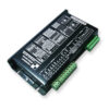
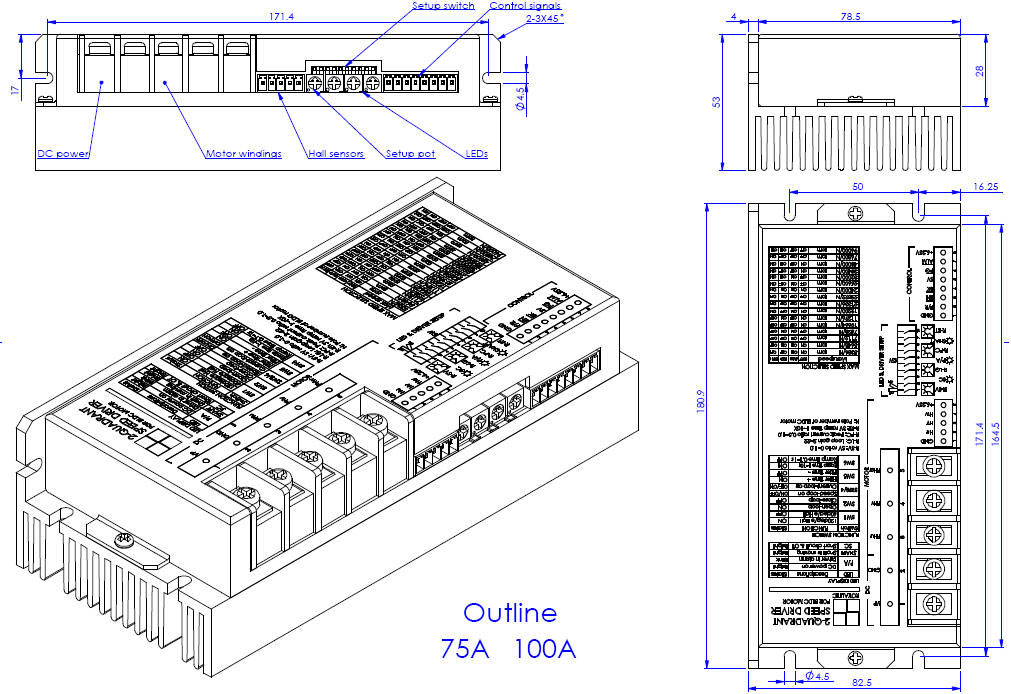
- 1. Control signals:
- F/R—–H or Open=Forward, L or Close=Reverse
- EN——H or Open=Disable, L or Close=Enable
- BK——H or Open=Running, L or Close=Brake
- SV——0~5V speed reference(112K input resistance)
- PG—–Speed pulse output(OC)
- ALM—Alarm output(OC)
- 2. Signal wire:
- Control signal cable and hall sensors cable can not be tied together with windings cable, otherwise, it will take interference. The long wire should be shielded wire.
- 3. Alarm conditions:
- a. Hall sensor signals are not correct.
- b. LV or OV for 1~3S.
- c. Short circuit and Over temperature of case (80℃)..
- d. Over load for 5~6s continuously.
- e. It can be reset by Turn-Off-On DC Power or Disable the driver once.
- 4. LED indicator:
- SC——–Bright=Short circuit , Dark=driver is OK
- P/A——-Bright=Driver is OK, Blink=Driver is in alarm
- SHAFT—-Bright=Motor shaft is moving, Dark=Motor shaft is in static
- 5. Braking operation:
- The motor speed must be less than the safe brake speed Ns when you brake the motor.
- For Y windings, Ns=√3 x Ip x RL x N/ (2x Vp)
- For △windings, Ns=IP x RL x N/ (2 x √3 x Vp)
- Ip=Peak current(A), RL=Line to line resistance of windings(Ohm), N=No-load speed(rpm), Vp=Rated voltage(V), Ns=Safe brake speed(rpm)
- 6. Safe F/R:
- If you change F/R of the driver rapidly, it will stop the power stage and motor will be free until the speed is detected as zero,and then to drive in correct direction. This means smooth reverse.
- 7. Safe start:
- If the motor speed is not detected as zero at power on, the driver will be free until the motor speed is zero.
- 8. Drive setup by pot and switch:
- R-SV pot=SV voltage ratio, R-LG pot=Loop gain, R-PC=Peak current ratio, R-RT pot=Ramp time
- SW1=60/120 Hall sensors, SW2=Open/Close loop, SW3,4=Speed/Current loop, SW5=Loop filter time, SW6=SV ramp time setting, SW7,8,9,10=Speed range setting.
- 9. Peak current selection:
- Ip>=2xIr or Ip>=4xPo/Vp, Ip is peak current of driver(A), Ir is rated current of motor(A), Po is rated output power of motor(W), Vp is rated voltage of driver(V)
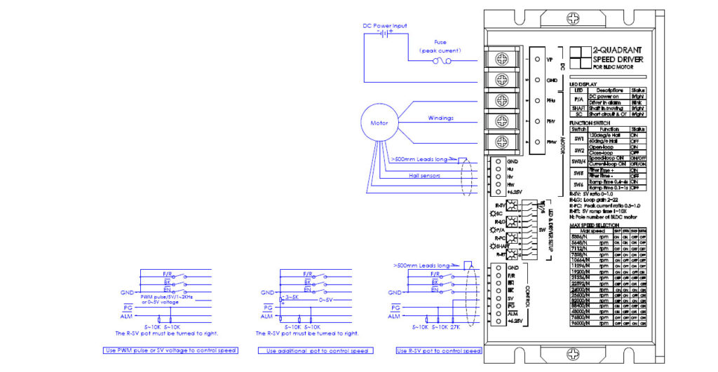
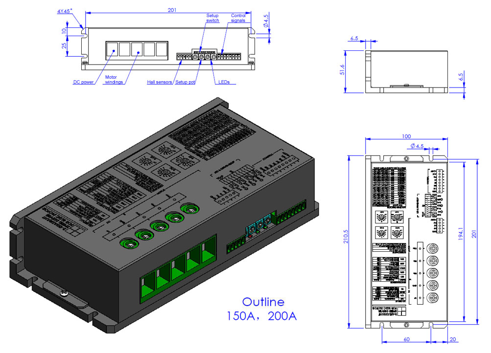
Outline
Customization
 |  |  |
| Heat sink | Motor tuning | Logo / brandmark |
| Item | Description |
|---|---|
| Heat Sink | Optional heat sinks can be installed upon request to enhance thermal performance. |
| Motor Tuning | We provide driver tuning services to optimize performance with motors of different pole counts, ensuring a perfect match for your application. |
| Logo & Brandmark | We offer OEM/ODM services, including printing your company logo or brandmark directly onto the driver’s frame. |
Frequently Asked Questions (FAQ)
Q: What is the main benefit of the “High Current” (H-Series)?
A: The “H-Series” is specifically designed to deliver exceptionally high peak currents (up to 200A) at low operating voltages (e.g., 12V, 24V, 48V). This makes it the ideal high current BLDC motor driver for battery-powered applications, like AGVs or electric vehicles, where high torque is needed without a high voltage supply.
Q: What does the 2-Quadrant (2Q) control mode mean?
A: 2-Quadrant (or 2Q) control means this high current BLDC motor driver can operate the motor in two directions: Forward Motoring (Q1) and Reverse Motoring (Q3). It controls speed and provides torque in both clockwise and counter-clockwise rotation, which is ideal for most automation tasks.
Q: What does “PI Closed-Loop” control mean for this driver?
A: This high current BLDC motor driver uses a PI (Proportional-Integral) algorithm for its speed control. It reads the Hall sensor feedback (PG output) and compares it to the set speed (SV), then automatically adjusts the power to maintain that speed, even if the load changes.
Q: How do I control the speed of this BLDC motor controller?
A: This BLSD-H is a high current BLDC motor driver that supports multiple speed control methods via the SV (Speed Voltage) input. You can use a 0-5V analog voltage signal, a PWM pulse signal, or connect an external potentiometer to the SV pin to adjust the speed. It also features parameter settings via onboard switches and pots.