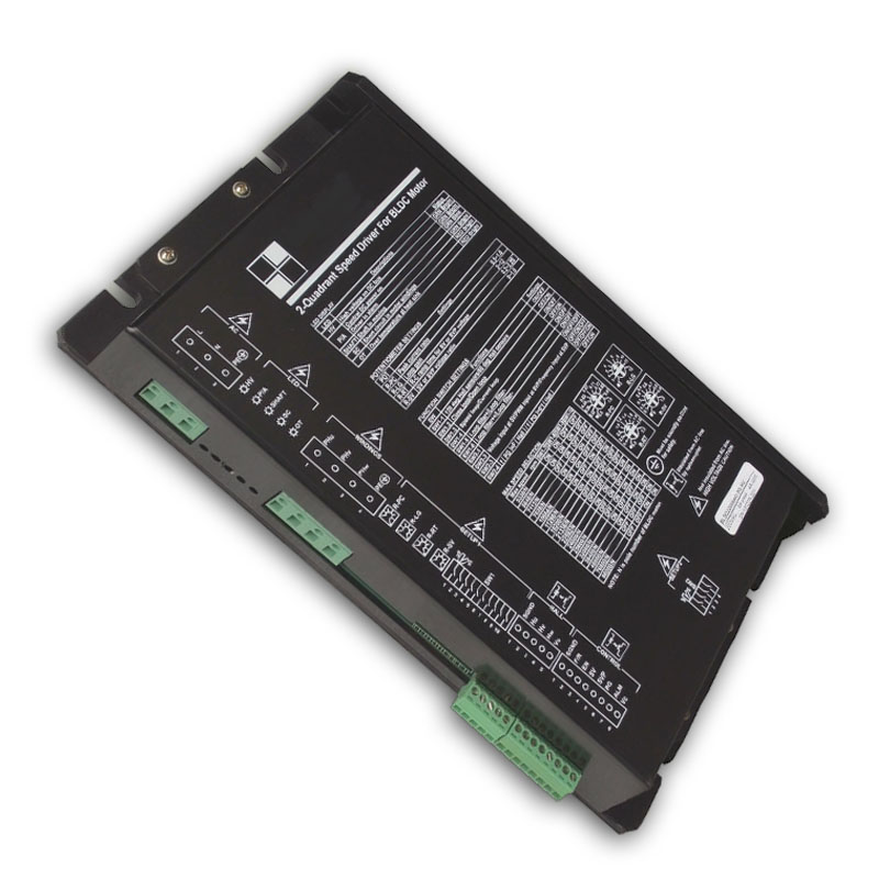
Brief Introduction
- Surface mounted technology to improve the reliability of the circuit.
- PLC interface, high voltage and wide voltage range.
- 0-10V analog voltage / pulse width signal / pulse frequency signal supports.
- Optoelectronic isolation for all the ports with over temperature, over current, short circuit, under voltage, over voltage and other protections.
- Military conformal coating for PCB surface, moisture, mold, dust-proof.
- Super safe and super reliable.
Definition of Part number:
| BLSD | 220 | 16 | ADC | 2Q | HV | T |
|---|---|---|---|---|---|---|
| BLDC drive | Rated Voltage | Peak current limit | AC/DC input ① | Control mode | Parameter ② | Temp ③ |
- ① AC/DC input: This code shows the DC Power input type of the drive: ADC=AC and DC dual purpose; DC = Normal DC input; LDC = Ultra low voltage DC input; WDC = Wide range DC input; AC = AC input.
- ② Parameter: This code shows the parameter type of the drive: S = Simple fixed parameter; N = Variable parameter; H = High current; SH = Small type high voltage; HV = High voltage.
- ③ Temp: This code shows the temperature range of the drive: T = -40 ~ +65 ℃ , None = -10 ~ +45℃ .
Note: In order to let the part number easier to read, Some part number code will not be shown in the specification table, a code “X” will be instead. The full part number will be provided in the quotation or the proforma invoice…
Specifications
Model
| Temp range (ºC) | Voltage range (VDC/VAC) | Peak Current adjustable (A) | Continuous Current adjustable (A) | 60º/120º Hall sensor | PWM f(kHz) | PI Close loop of speed or current | RC Ramp time (S) | Reference Input Range | LV/OV Alarm | Alarm diag output | PG speed pulse output | Current/ speed loop switch | Setting by switch and potentio-meter | SC/ OT | Safe F/R | Safe Start |
|---|---|---|---|---|---|---|---|---|---|---|---|---|---|---|---|---|---|
| BLSD11008ADC-2Q-HV-X | -10~+45 or -40~+65 | AC 110 (DC 60-195) | 4~8 | 2~4 | √
| 16 | √
| √
| 0-10V or PWM or 0-3KHz pulse customizable | √
| √
| 4p@8-pole or 24p@8-pole | √ | √ | √ | √ | √ |
| BLSD11016ADC-2Q-HV-X | 8~16 | 4~8 | 16 | ||||||||||||||
| BLSD11024ADC-2Q-HV-X | 12~24 | 6~12 | 16 | ||||||||||||||
| BLSD22008ADC-2Q-HV-X | AC 220 (DC 60-385) | 4~8 | 2~4 | 16 | |||||||||||||
| BLSD22016ADC-2Q-HV-X | 8~16 | 4~8 | 16 | ||||||||||||||
| BLSD22024ADC-2Q-HV-X | 12~24 | 6~12 | 16 |
* All the drivers in the above table can use AC and also DC input. When use AC, the driving voltage mode in the motor port is DC, the voltage is 1.4 times than input AC voltage. When use DC, the driving voltage mode in the motor port is DC, the voltage is same with input DC voltage
In-Depth Applications for this High Voltage BLDC Motor Driver
The BLSD-HV Series is a high voltage BLDC motor driver designed for machinery that operates directly from a 110V or 220V AC wall outlet, eliminating the need for a large external DC power supply. Its “HV” (High Voltage) and “ADC” (AC/DC input) capabilities make it a powerful and efficient solution. Key application areas include:
- Industrial Machinery: Ideal for construction spraying machines, PCB board cutting machines, and textile equipment that require high, continuous power from an AC source.
- Automation & Conveying: This high voltage BLDC motor driver can drive large conveyor systems and sorting machines that require high torque at high voltage.
- Pumps & Ventilation: Operates large-scale industrial fans, blowers, and pumps efficiently, running directly from the AC main supply using this high voltage BLDC motor driver.
Control Interface and Features
1. Power Supply Port:
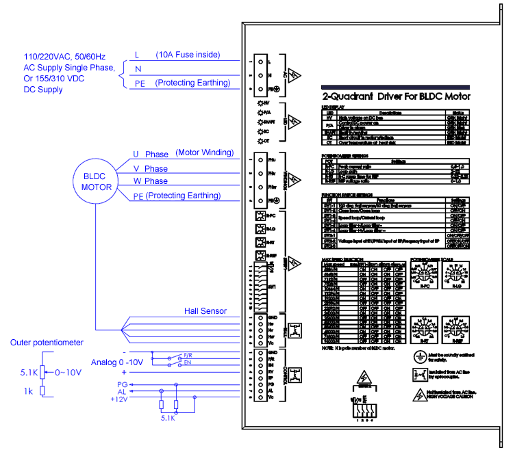
A wide range AC or DC power supply of AC45-275V/50-60Hz in single phase, DC60-385V can be used for the driver. The PE point of driver and power supply system must be connected reliably for safety. Please take attention to the high voltage warning.
2. Motor Windings Port:
Connect three phases of windings to the U/V/W points in correct sequence. PE on motor case must be connected to PE point of this port for safety. Please take attention to the high voltage warning.
3. Motor Hall Sensor Port:
Connect Hall sensors Hu/Hv/Hw to the port in correct sequence. This port is insulated from inside circuit by optocoupler and Vc supply is provided by driver.
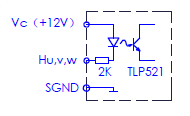
4. Control Signal Port:
This port is insulated from inside circuit by optocoupler and one line isolated 12V power supply is provided by driver for external use, the current is less than 50mA
F/R: Rotating direction control. Forward=open ,Reverse=connect to SGND
The driver can provide safety forward/reverse control. If the direction is changed suddenly when the motor is running, the motor will cut down the power and sliding to zero speed smoothly and then change rotating direction in order to avoid the shock impact. At the moment that the driver power up, if the speed is not zero, then it will start until the speed is zero.
EN: Enable control function. Enable when optocoupler conduct. The driver can only be work when enable. The alarm can be reset by EN=disable once

SV:Analog reference voltage input of 0~10V. Input impedance 200K. It is insulated from inside circuit by a linear optocoupler.
SVP:Digital reference pulse input of 0~3KHz frequency or 0~100% PWM@50-1KHz .
PG:Speed pulse output in OC(30Vmax/5mA). This signal can be made in synchronize to one phase hall sensor signal or 6 times frequency multiplier. The motor speed is in proportion to the frequency. Motor speed(rpm)=PG frequency(Hz)x120/N. N is the pole number of motor. Or, motor speed(rpm)=PG frequency(Hz)x120/N/6 (6 times frequency multiplier).
AL:Alarm output in OC(30Vmax/5mA). The driver has self-diagnostic function. When the following conditions come, the alarm comes up, and optocoupler will conduct.
For items of NO.1~5, green LED P/A will be blinking. The alarm can be reset by EN=disable once.
For items of NO.6~7, red LED will brighten. The alarm can be reset only you Off-on supply again.
1. Incorrect Hall signal 2. Low control voltage 3. OT at main chip 4. LV or OV at power supply voltage 5. current continuous overload (Peak current limiting) over 6 seconds 6. Case temperature over 7. Short circuit in motor windings.
Vc,SGND: One line isolated 12V power supply is provided by driver for external use, the current is less than 50mA
5. LED Display:
HV: DC bus voltage instruction LED. Green color LED. High voltage on DC power line when brighten. Warning: Do not open the case and touch the high voltage parts when this LED brightens.
P/A: Green color LED. Control supply and Alarm. LED will be blinking in alarm state.
SHAFT: Green color LED. When motor shaft is moving, LED will brighten, When moving stopped, LED turns dark. In order to avoid the danger, do not touch the shaft and the related components when this LED brightens.
SC: Short circuit indicator LED. Red color LED. When Short circuit in windings of motor, LED will brighten. The alarm can be reset only you Off-on supply again after removal of fault.
OT: Over temperature indicator LED. Red color LED. When over temperature at driver case, LED will be brighten and alarm. The alarm can be reset only you Off-on supply again after apply the cooling measures.
6. Potentiometers:
R-PC:Peak current ratio,50%-100% R-LG:Loop gain,2-22 R-RT:Ramp time,0.2-2.2S R-SV:Reference ratio,0-100%. Usually used for precisely calibrating in full speed control instructions. Also can be used for internal speed control potentiometer by its attenuation effect.
7. Switches:
SW1-1:ON=120°Hall sensors,OFF=60°Hall sensors
SW1-2:ON=Close loop,OFF=Open loop
SW1-3/4:ON/OFF=Speed loop,OFF/ON=Current loop
SW1-5/6:ON=Increase loop filter time,OFF=Decrease loop filter time
SW1-7/8/9/10:Max speed range setting. It’s related to the motor poles, please check the table printed in the driver case.
SW2-1/2/3:ON/OFF/OFF=0-10V analog input at SV,OFF/ON/OFF=0~100% PWM (1~2KHz) input at SVP,OFF/OFF/ON=0~3KHz pulse frequency input at SVP.
SW2-4:ON=PG frequency is 6x Hall sensor frequency per phase
OFF=PG frequency is 1x Hall sensor frequency per phase

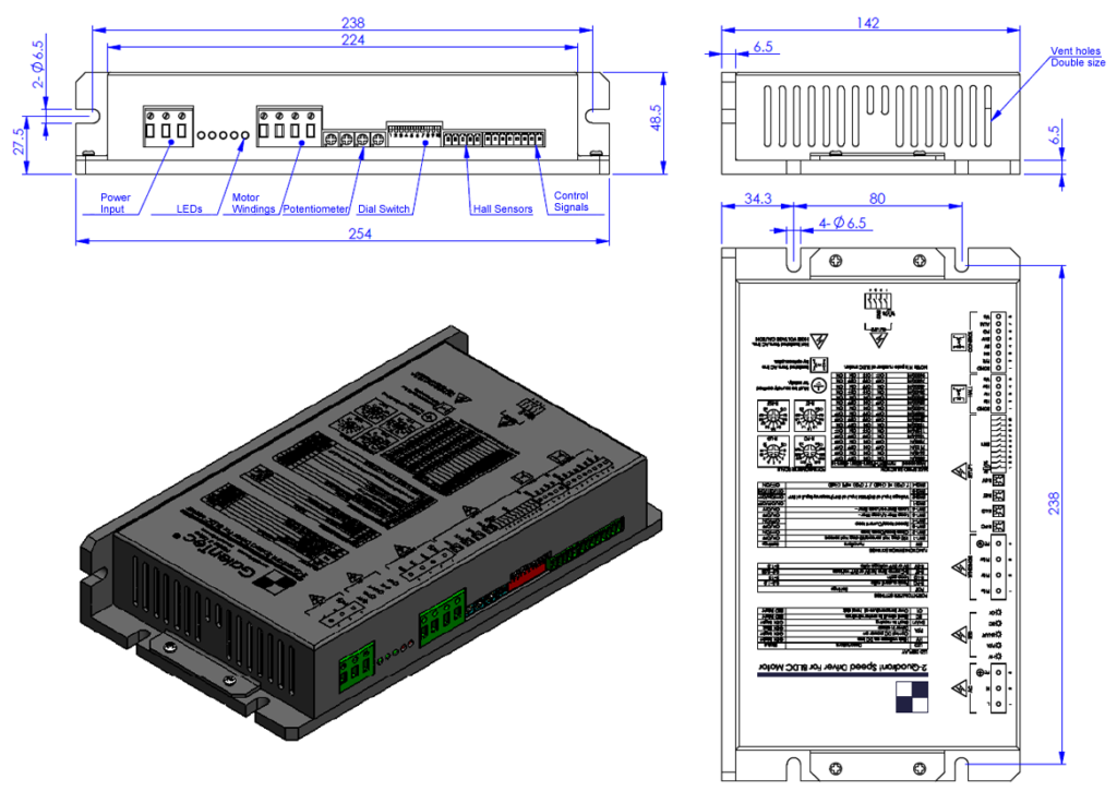
Outline
Customization
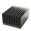 | 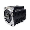 |  |
| Heat sink | Motor tuning | Logo / brandmark |
| Item | Description |
|---|---|
| Heat Sink | Optional heat sinks can be installed upon request to enhance thermal performance. |
| Motor Tuning | We provide driver tuning services to optimize performance with motors of different pole counts, ensuring a perfect match for your application. |
| Logo & Brandmark | We offer OEM/ODM services, including printing your company logo or brandmark directly onto the driver’s frame. |
Frequently Asked Questions (FAQ)
Q: What is the main benefit of the “High Voltage” (HV-Series)?
A: The “HV-Series” is an industrial-grade high voltage BLDC motor driver. Its key benefit is the AC/DC dual-purpose input. It can be connected directly to a 110VAC or 220VAC power source (or high voltage DC), allowing it to drive powerful motors (up to 24A) without a separate, large DC power supply, which saves cost and space.
Q: What does “PI Closed-Loop” control mean for this driver?
A: This high voltage BLDC motor driver uses a PI (Proportional-Integral) algorithm for its speed or current control. It reads the Hall sensor feedback (PG output) and compares it to the set speed (SV), then automatically adjusts the power to maintain that speed, even if the load changes.
Q: How do I control the speed of this BLDC motor controller?
A: This BLSD-HV high voltage BLDC motor driver is highly flexible. You can control the speed using a 0-10V analog signal (at SV), a PWM pulse signal, or a 0-3KHz pulse frequency signal (at SVP), selectable via DIP switch.
Q: What safety features does this bldc motor drive include?
A: This high voltage BLDC motor driver is built for safety. It includes reliable protections for incorrect Hall signals, low/over voltage (LV/OV), over-temperature (OT), over-load (OL), and short-circuit (SC), with alarm (AL) and LED indicators for diagnostics.
