
Definition of Part number:
| BLSD | 24 | 05 | DC | 2Q | S | 8 | 040 | 0.5 | T | F | P | A |
|---|---|---|---|---|---|---|---|---|---|---|---|---|
| BLDC drive | Rated Voltage | Peak current limit | DC input ① | Control mode | Parameter ② | Pole | Max speed range ③ | SV ramp RC time | Temp ④ | PG type ⑤ | Speed regulation type ⑥ | Sensor type ⑦ |
- ① DC input: This code shows the DC Power input type of the drive: DC = Normal DC input; LDC = Ultra low voltage DC input; WDC = Wide range DC input; AC = AC input; ADC = AC and DC dual purpose.
- ② Parameter: This code shows the parameter type of the drive: S = Simple fixed parameter; N = Variable parameter; H = High current; SH = Small type high voltage; HV = High voltage.
- ③ Max speed range: This code shows the max speed range of the drive, the unit is rpm/100.
- ④ Temp: This code shows the temperature range of the drive: T = -40 ~ +65 ℃ , None = -10 ~ +45℃ .
- ⑤ PG type: This code shows the PG type: F = PG 1x hall sensor signal/phase, None= 6 x hall sensor signal/phase.
- ⑥ Speed regulation type: This code shows the speed regulation type: P = 0-3KHz speed regulation, None = voltage command..
- ⑦ Sensor type: This code shows the hall sensor degree of the drive: A = 60° Hall sensor, None = 120° Hall sensor.
Note: In order to let the part number easier to read, Some part number code will not be shown in the specification table, a code “X” will be instead. The full part number will be provided in the quotation or the proforma invoice…
Specifications
| Model | Temp range (ºC) | Voltage range (VDC) | I-pk (A) | I-con (A) | 60º/120º Hall sensor | PWM f(kHz) | PI Close loop of speed | SV Ramp time (S) | SV Range (V) | LV /OV | Alm | PG | Heat Sink |
|---|---|---|---|---|---|---|---|---|---|---|---|---|---|
| BLSD1205DC-2Q-S-X-XXX-XX | -10~+45 -40~+65 | 9~16 | 5 | 2.5 | √ | 15 | √ | 0.1~1.0 | 0~5 | √ | √ | 24p @8-pole | X |
| BLSD1210DC-2Q-S-X-XXX-XX | -10~+45 -40~+65 | 9~16 | 10 | 5 | √ | 15 | √ | 0.1~1.0 | 0~5 | √ | √ | 24p @8-pole | X |
| BLSD1215DC-2Q-S-X-XXX-XX | -10~+45 -40~+65 | 9~16 | 15 | 7.5 | √ | 15 | √ | 0.1~1.0 | 0~5 | √ | √ | 24p @8-pole | X |
| BLSD1220DC-2Q-S-X-XXX-XX | -10~+45 -40~+65 | 9~16 | 20 | 10 | √ | 15 | √ | 0.1~1.0 | 0~5 | √ | √ | 24p @8-pole | X |
| BLSD1230DC-2Q-S-X-XXX-XX | -10~+45 -40~+65 | 9~16 | 30 | 15 | √ | 15 | √ | 0.1~1.0 | 0~5 | √ | √ | 24p @8-pole | √ |
| BLSD2405DC-2Q-S-X-XXX-XX | -10~+45 -40~+65 | 17~32 | 5 | 2.5 | √ | 15 | √ | 0.1~1.0 | 0~5 | √ | √ | 24p @8-pole | X |
| BLSD2410DC-2Q-S-X-XXX-XX | -10~+45 -40~+65 | 17~32 | 10 | 5 | √ | 15 | √ | 0.1~1.0 | 0~5 | √ | √ | 24p @8-pole | X |
| BLSD2415DC-2Q-S-X-XXX-XX | -10~+45 -40~+65 | 17~32 | 15 | 7.5 | √ | 15 | √ | 0.1~1.0 | 0~5 | √ | √ | 24p @8-pole | X |
| BLSD24020DC-2Q-S-X-XXX-XX | -10~+45 -40~+65 | 17~32 | 20 | 10 | √ | 15 | √ | 0.1~1.0 | 0~5 | √ | √ | 24p @8-pole | X |
| BLSD2430DC-2Q-S-X-XXX-XX | -10~+45 -40~+65 | 17~32 | 30 | 15 | √ | 15 | √ | 0.1~1.0 | 0~5 | √ | √ | 24p @8-pole | √ |
| BLSD3605DC-2Q-S-X-XXX-XX | -10~+45 -40~+65 | 27~45 | 5 | 2.5 | √ | 15 | √ | 0.1~1.0 | 0~5 | √ | √ | 24p @8-pole | X |
| BLSD3610DC-2Q-S-X-XXX-XX | -10~+45 -40~+65 | 27~45 | 10 | 5 | √ | 15 | √ | 0.1~1.0 | 0~5 | √ | √ | 24p @8-pole | X |
| BLSD3615DC-2Q-S-X-XXX-XX | -10~+45 -40~+65 | 27~45 | 15 | 7.5 | √ | 15 | √ | 0.1~1.0 | 0~5 | √ | √ | 24p @8-pole | X |
| BLSD3620DC-2Q-S-X-XXX-XX | -10~+45 -40~+65 | 27~45 | 20 | 10 | √ | 15 | √ | 0.1~1.0 | 0~5 | √ | √ | 24p @8-pole | X |
| BLSD3630DC-2Q-S-X-XXX-XX | -10~+45 -40~+65 | 27~45 | 30 | 15 | √ | 15 | √ | 0.1~1.0 | 0~5 | √ | √ | 24p @8-pole | √ |
| BLSD4805DC-2Q-S-X-XXX-XX | -10~+45 -40~+65 | 37~55 | 5 | 2.5 | √ | 15 | √ | 0.1~1.0 | 0~5 | √ | √ | 24p @8-pole | X |
| BLSD4810DC-2Q-S-X-XXX-XX | -10~+45 -40~+65 | 37~55 | 10 | 5 | √ | 15 | √ | 0.1~1.0 | 0~5 | √ | √ | 24p @8-pole | X |
| BLSD4815DC-2Q-S-X-XXX-XX | -10~+45 -40~+65 | 37~55 | 15 | 7.5 | √ | 15 | √ | 0.1~1.0 | 0~5 | √ | √ | 24p @8-pole | X |
| BLSD4820DC-2Q-S-X-XXX-XX | -10~+45 -40~+65 | 37~55 | 20 | 10 | √ | 15 | √ | 0.1~1.0 | 0~5 | √ | √ | 24p @8-pole | √ |
| BLSD4830DC-2Q-S-X-XXX-XX | -10~+45 -40~+65 | 37~55 | 30 | 15 | √ | 15 | √ | 0.1~1.0 | 0~5 | √ | √ | 24p @8-pole | √ |
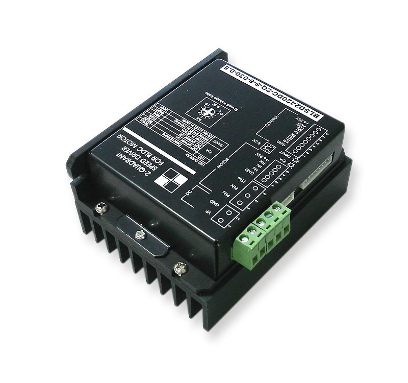
In-Depth Applications for this Fixed Parameter BLDC Motor Driver
The BLSD-S Series is a versatile and economic driver designed for reliable industrial systems. Its “S” designation signifies a simple, fixed parameter setup, making it ideal for high-volume OEM applications where ease of use and reliability are paramount. Key application areas include:
- Automation & Conveyors: Provides precise speed control (using 0-5V analog signals) for conveyor belts, sorting machines, and other automated equipment.
- Industrial Machinery: This BLDC motor controller is perfect for textile machines, packaging systems, and winding machines that require reliable, continuous operation.
- Pumps & Ventilation: Operates fans and pumps efficiently, utilizing the driver’s variable speed control (SV) to match system demand and save energy.
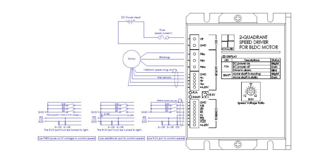
Control Interface and Features
- 1. Control signals:
- F/R—–H or Open=Forward, L or Close=Reverse
- EN——H or Open=Disable, L or Close=Enable
- BK——H or Open=Running, L or Close=Brake
- SV——0~5V speed reference(112K input resistance)
- PG—–Speed pulse output(OC)
- ALM—Alarm output(OC)
- 2. Hall sensors cable:
- Hall sensors cable can not be tied together with windings cable.
- 3. Alarm conditions:
- Hall sensor signals are not correct.
- LV or OV for 2~3S.
- Over load for 6s continuously.
- It can be reset by Turn-Off-On DC Power or Disable the driver once.
- 4. LED indicator:
- P/A——-Bright=Driver is OK, Blink=Driver is in alarm
- SHAFT—-Bright=Motor shaft is moving, Dark=Motor shaft is in static
- 5. Braking operation:
-
The motor speed must be less than the safe brake speed Ns when you brake the motor.
- For Y windings, Ns=√3 x Ip x RL x N/ (2 x Vp)
- For △windings, Ns=IP x RL x N/ (2 x √3 x Vp)
- Ip=Peak current(A), RL=Line to line resistance of windings(Ohm), N=No-load speed(rpm), Vp=Rated voltage(V), Ns=Safe brake speed(rpm)
- 6. Peak current selection:
- Ip>=2xIr or Ip>=4xPo/Vp, Ip is peak current of driver(A), Ir is rated current of motor(A), Po is rated output power of motor(W), Vp is rated voltage of driver(V)
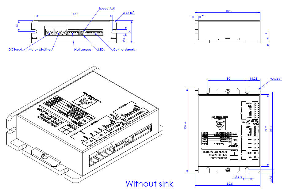
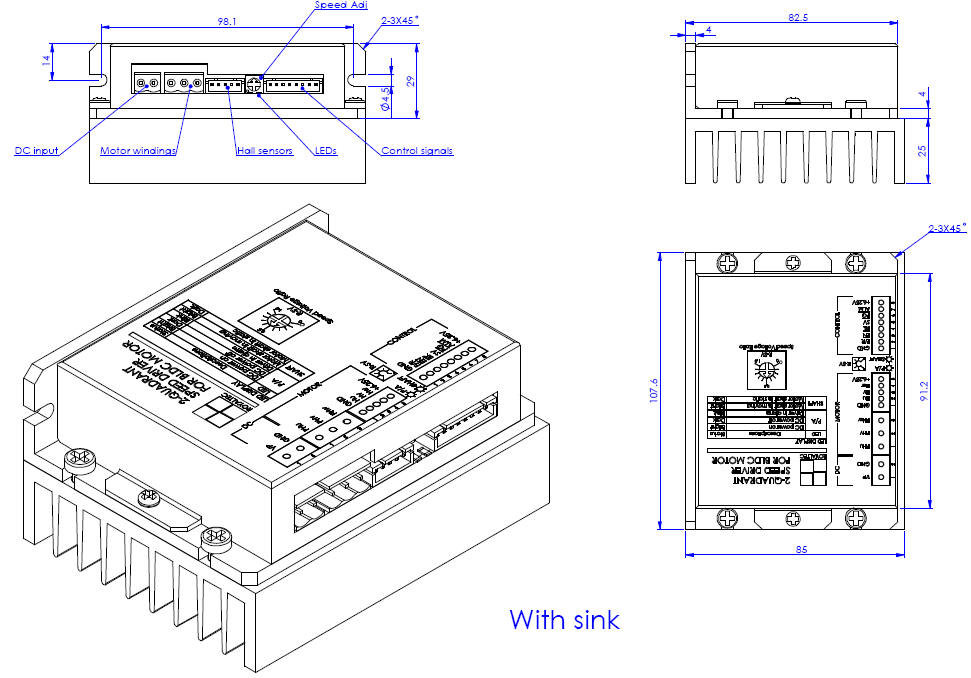
Outline
Customization
 |  |  |
| Heat sink | Motor tuning | Logo / brandmark |
| Item | Description |
|---|---|
| Heat Sink | Optional heat sinks can be installed upon request to enhance thermal performance. |
| Motor Tuning | We provide driver tuning services to optimize performance with motors of different pole counts, ensuring a perfect match for your application. |
| Logo & Brandmark | We offer OEM/ODM services, including printing your company logo or brandmark directly onto the driver’s frame. |
Frequently Asked Questions (FAQ)
Q: What does “Fixed Parameter” (S-Series) mean?
A: “Fixed Parameter” means this BLDC motor driver is pre-configured at the factory for optimal performance with a specific range of motors. It simplifies installation, as it does not require complex software setup, making it a highly reliable and cost-effective choice for OEM integration.
Q: What does the 2-Quadrant (2Q) control mode mean?
A: 2-Quadrant (or 2Q) control means this driver can operate the motor in two directions: Forward Motoring (Q1) and Reverse Motoring (Q3). It controls speed and provides torque in both clockwise and counter-clockwise rotation, which is ideal for most automation tasks.
Q: What does “PI Closed-Loop” control mean for this driver?
A: This brushless dc motor driver uses a PI (Proportional-Integral) algorithm for its speed control. It reads the Hall sensor feedback (PG output) and compares it to the set speed (SV), then automatically adjusts the power to maintain that speed, even if the load changes.
Q: How do I control the speed of this BLDC motor controller?
A: The BLSD-S fixed parameter BLDC motor driver supports multiple speed control methods via the SV (Speed Voltage) input. You can use a 0-5V analog voltage signal, a PWM pulse signal, or connect an external potentiometer (3-5K) to the SV pin to adjust the speed. It also accepts Enable (EN), Forward/Reverse (F/R), and Brake (BK) signals.
Q: What size brushless dc motor can this drive handle?
A: The BLSD-S Series is a high-current bldc motor drive, available in models that can handle up to 30 Amps peak current, making it suitable for a wide range of DC motors within its voltage class (9-55V).