
1. Summary
BLSD-D-02-H BLDC motor driver is a closed-loop speed controller, which uses IGBT and MOS power, uses the Hall signal of the DC brushless motor to perform double-loop speed control, and has a PID speed regulator in the control link. The system control is stable and reliable.
It can always reach the maximum torque at low speed, and the speed control range is 150~10000rpm.
Features
- PID speed, current double loop regulator
- With best price performance ratio
- 20KHZ chopper frequency
- Electrical stop to ensure the quickly action
- Over load radio larger than 2, the torque can always reach the maximum at low speed.
- Fault alarm function with Over voltage, Under voltage, Over current, Over temperature, and Hall signal illegal.
Product Characteristic
- Input voltage: 24~48VDC. (Under the power<2000W)
- Accelerate time constant(default) : 2 seconds
- Motor stall protection time: 3 seconds, other can be customized
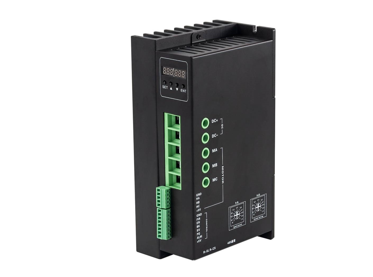
2. Terminal and Control Signal
Control Terminal
| No. | Terminal Name | Description |
| 1 | COM | COM terminal |
| 2 | F/R | CW/CCW terminal |
| 3 | EN | Stop/Start terminal |
| 4 | BR | Brake terminal |
| 5 | SV | Analogy signal input terminal |
| 6 | PG | Speed output terminal |
| 7 | ALARM | Alarm output terminal |
| 8 | +5V | +5V power output terminal |
Hall Signal Terminal
| No. | Name | Description |
| 1 | GND | Hall sensor Negative |
| 2 | HA | Hall sensor A phase |
| 3 | HB | Hall sensor B phase |
| 4 | HC | Hall sensor C phase |
| 5 | +5V | Hall sensor Positive |
Motor Connection Terminal
| No. | Name | Description |
| 1 | DC+ | DC+ |
| 2 | DC- | DC- |
| 3 | FG | Ground wire |
| 3 | MA(U) | Winding U phase(A) |
| 4 | MB(V) | Winding V phase(B) |
| 5 | MC(W) | Winding W phase(C) |
3. Control Signal
| No. | Terminal Name | Description |
| 1 | GND | Signal ground |
| 2 | F/R | CW/CCW terminal |
| 3 | EN | Stop/Start terminal |
| 4 | BK | Brake terminal |
| 5 | SV | Analogy signal input terminal |
| 6 | PG | Speed output terminal |
| 7 | ALM | Alarm output terminal |
| 8 | +5V | +5V power output terminal |
GND: Signal ground
F/R: Forward and reverse control, reverse when connected to GND, forward if not connected, turn off EN when switching between forward and reverse.
EN: Enable control: EN connect to the ground, motor turn (online state), EN not connected, motor does not turn (offline state).
BK: Brake control: When it is not grounded and works normally, when it is grounded, the motor is electrically braked. When the load inertia is large, it should be used pulse width signal mode, control the brake by adjusting the pulse width amplitude.
SV: ADJ: External speed attenuation: can be attenuated from 0~100%, when the external speed command is connected to 6.25V, the potentiometer can be used to speed and test the motor.
PG: Motor speed pulse output: When the pole pair is P, 6P pulses per revolution (Open Collector input).
ALM: Alarm output: When the circuit is in the alarm state, the output is low (Open Collector output).
+5V: Speed regulation voltage output, the potentiometer can be continuously adjusted at SV and GND.
Dial code switch: Adjust the motor speed gain and the speed range from 0 to 100%.
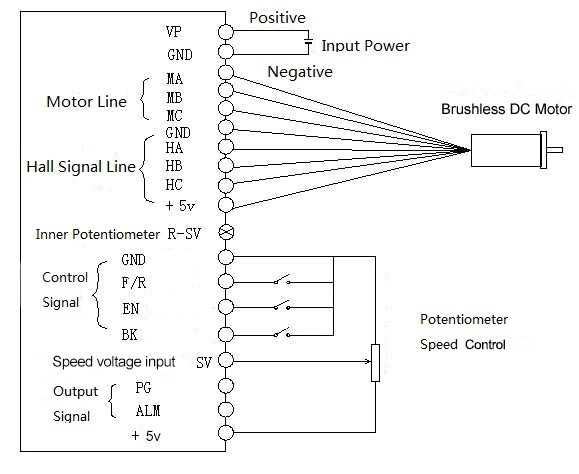
Connection Diagram of motor and driver
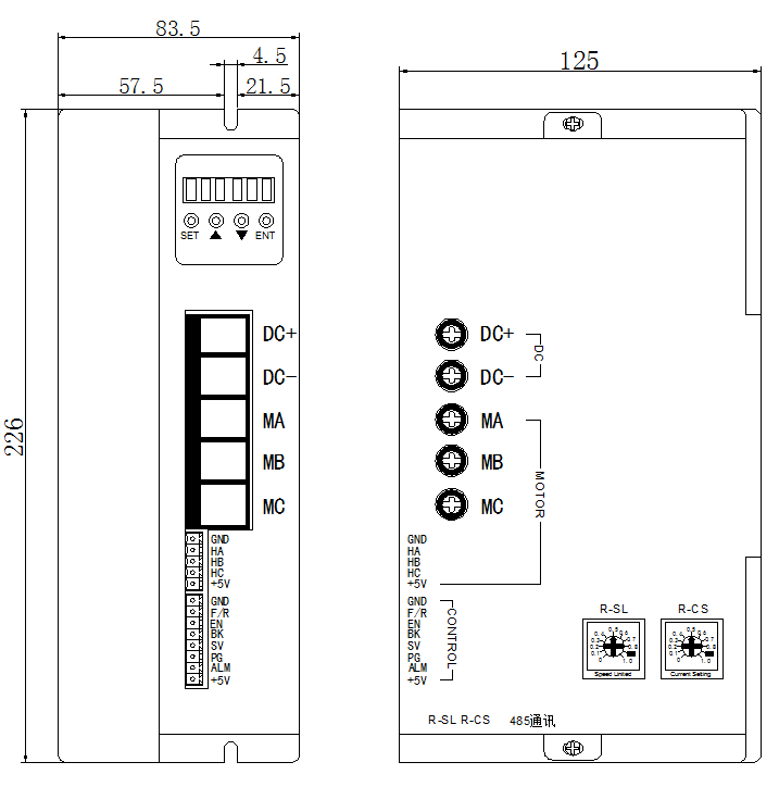
4. Mounting Dimension
5. Function and Usage
Choose any of the below speed command:
Build-in potentiometer: Speed reduced while CCW potentiometer, otherwise speed increased. Set the potentiometer at minimum while use the external speed command.
External potentiometer: Connect on the GND and +5V of the drives, speed can be adjusted on external potentiometer ((5K~100K) when connect SV terminal. Input simulate voltage through other control command (e.x. PLC, SCM etc.) to SV terminal to achieve the speed adjust as well (relative GND). The range of the SV terminal is DC OV~+5V, the relevant motor speed is 0~rated speed.
External digital signal speed regulation: Add 5V between SV and GND, speed can be adjusted by PWM control between the 1KHz~2KHz, motor speed is influenced by duty. At this time, by adjusting the R-SV potentiometer, SV digital signal amplitude can be 0~1.0 ratio attenuation processing. Generally, adjust R-SV to 1.0, SV input digital signal without attenuation processing.
Motor running/stop control (EN)
Control the brushless motor to run or stop by controlling the terminal “EN” and “GND” connecting. The motor will running when we connect the terminal “EN” to “GND”; if shut down, the motor will stop, and the stopping time will decided by the motor inertia and load adding on the motor.
Motor rotation direction control(F/R)
Control the motor rotation direction by controlling the terminal “F/R” and “GND” connecting. When shut off terminal “F/R” to terminal “GND”, the motor will run at CW (view from motor output side), and when connect on, the motor will run at another direction. For avoiding to damage the driver, please stop the motor running and then change the motor rotation direction.
Brake the motor to stop(BK)
Motor stop can be controlled by connect BK and GND terminal. When shut off the BK and GND terminal, motor running, otherwise motor will fast stop. Motor stopping time is decided by the motor inertia and load adding on the motor. If it is unnecessary to fast stop the motor, please don’t use this function since it has some electrical and mechanical impact on the motor and controller.
Speed signal output(PG)
The speed pulse output port is OC, output 30V/10mA max. You can connect with a resistance (3K ohm ~10K ohm) between signal and input power to get the pulse signal, this port will output serial pulses which has fixed extent ( it is 50uS). This output pulse from every rotation of motor is 3 x N, “N” means the total pole number of the magnet.For example, 2 pair of poles,means 4 poles motor, 12 pulses per turning, when the motor speed is 500rpm, the pulses out from the PG is 6000.
Alarm output
The alarm output port is OC, output 30V/10mA max. You can connect with a resistance (3K ohm ~10K ohm) between signal and input power to get the alarm signal. When alarm, this port and the GND is connecting (Low voltage), and the controller will stop working and keep in alarm status.
Driver failure
Drivers enter to protection status while inner overload or over current, drivers and motor will stop automatic, the blue led will flashed on the driver. The alarm can be released by reset the enable terminal (shut off EN and GND) or switched off. Please check the motor connection wires when failure.
6. Display and keyboard
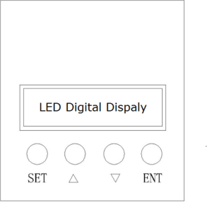
Display and Keyboard Operation
Remark: “SET”:Start/Stop, (backspace)
“△” :“+”,Plus 1
“▽” :“-” , Minus 1
“ENT”:“ENTER” (Recall setting parameter)
6.1 Parameter Setting Sequence
Please insure that the motor is under the stop situation when set the parameter. That is, in the case of panel mode, the motor is in the stop state or an external port mode, the motor is enabled to disconnect.
- In standby condition, press “ENTER” to call out the system parameters, press “ENTER” again, it will call out the parameter value.
- Press “△”or “▽”to the parameter number. Press “SET” to return to standby mode if there is no value need to change.
- Press “ENTER” to show the parameter setting value. Press “SET” to return to standby mode if there is no need to change value.
- Press“△”or “▽” to change the value demanded.
- Press “ENTER” to save the changes, then press “SET” to return to standby mode.
Note: At setting mode, it will return to display interface if there is no press within one minute.
6.2 Working mode
Motor works at two modes. One is the panel mode, the other is external terminal control. The motor runs as the setting, LED digital display shows the speed of motor. Under the panel mode, Press “SET” to start/stop the motor, long press “△”or “▽” to acceleration or deceleration speed, press “ENTER” to insure and know the running speed. The motor runs as setting speed.
6.3 Protect mode
While Motor operates abnormally, display will show Err×
(1) Err-01: motor stall
(2) Err-02: over current
(3) Err-04: hall fault
(4) Err-05: motor stall and hall fault
(5) Err-08: under-voltage
(6) Err-10: over-voltage
(7) Err-20: peak current alarm
(8) Err-40: temperature alarm
6.4 Drives parameter setting:
| P00X:Operating Parameter | |||||
| Function Code | Function Name | Setting Range | Unit | Default value | Change |
| P000 | Control mode | 00 non inductive external control mode 18 non inductive mode panel control and 485 communication control mode 40 forced sensing external control mode 58 inductive mode panel control mode and 485 communication control mode | 40 forced sensing external control mode | ||
| P001 | Pair of Pole | 1~255 | Pairs | 2 |  |
| P002 | Rated Speed | 1~65535 (external port mode effective ) | RPM | 3000 | |
| P003 | Display mode | 00: speed display | 00 | | |
| P004 | starting torque | 1~255 | 16 | | |
| P005 | Initial speed w/o sensor start | 1~255 | 04 | | |
| P006 | Acceleration time | 1~255 | 0.1S | 0 | |
| P007 | Deceleration time | 1~255 | 0.1S | 0 | |
| P008 | Current setting | 1~255 | 44 | ||
| P009 | Temperature alarm setting | 1~255 | 34 | ||
| P010 | Panel speed setting | 1~65535 only external port mode effective | RPM | 2000 | |
| P011 | Brake force | 0-1023 | 1023 | ||
| P012 | Site address | 0~250 | 1 | ||
| P013 | Reserved | ||||
| P014 | Current adjusting parameter | 0-FF | Hexadecimal | 3A | |
| P015 | Reserve | ||||
| P016 | Reserve | ||||
7. System Usage
Connect on the wires of the motor and driver (motor winding wires, Hall wires and power lines) strictly as request. It can not achieve the CW and CCW through changing the wires connection like asynchronous motor. The motor will run abnormality with the wrong wires connection, like brushless motor will shake much or heat quickly (the temperature will up to 80 degree in seconds to 2 min.),and will damage the motor and driver.
Please run the motor while connect the power supply, Hall wires and drive power supply. Firstly set the potentiometer to the minimum, press the start switch, increase the motor potentiometer a little, the motor should run. If the motor does not run, or shaking, maybe did the wrong wires connection, please recheck the brushless motor wires till the motor running normally.
8. Communication Mode
This communication model is used standard Mod bus protocol, implement national standards GB/T 19582.1 – 2008. It is using RS485 two-wire serial link communication, Physical interface uses two 3.81mm spacing 3 core Phoenix terminals, serial connection is very convenient. Transmission mode is RTU, testing mode is CRC, CRC start word is FFFFH. Data mode is 8 bit asynchronous serial, 1 is stop bit, without invalid bit. Currently there is only one communication speed 9600bps,
| No. | address | name | Setting range | Default | unit | |
| 00 | $8000 | First byte: control bit state Second byte: Hall angle and pair of poles | First byte: Bit0:EN Bit1:FR Bit2:BK Bit3:NW1 Bit4:NW Bit5:KHX Bit6:HR60 Bit7:KH Second byte: Bit0-7: pair of poles 1-255 | 00H 02H | ||
| 01 | $8001 | Maximum speed in analog adjustment | 0-65535 | 3000 | RPM | |
| 02 | $8002 | First byte: start torque Second byte: start speed without sense start | 1-255 1-255 | 10H 04H | ||
| 03 | $8003 | First byte: accelerate time Second byte: decelerate time | 1-255 | 10 10 | 0.1s | |
| 04 | $8004 | First byte: max. Current Second byte: temperature alarm point | 35H 30H | |||
| 05 | $8005 | External speed setting | 0-65535 | 2000 | RPM | |
| 06 | $8006 | Brake force | 0-1023 | 1023 | ||
| 07 | $8007 | First byte: site address Second byte: reserved | 1-250 | 1 0 | ||
| 08-0F | $8008-$800F | Segmental speed value | ||||
| 10-17 | $8010-$8017 | reserved | ||||
| 18 | $8018 | Real speed | ||||
| 19 | $8019 | First byte: bus voltage Second byte: bus current | ||||
| 1A | $801A | First byte: control port state Second: analog port value | Bit0:SW1 Bit1:SW2 Bit2:SW3 Bit3:SW4 | |||
| 1B | $801B | First byte: fault state Second byte: motor running state | Bit0: stall Bit1: over current Bit2:hall abnormality Bit3:low bus voltage Bit4:over bus voltage Bit5:peak current alarm Bit6:temperature alarm Bit7:reserve | |||
| 1C | $801C-$801F | Reserve | ||||
| 20 | $8020 above illegal |
Site address 8000H-8017H Read-write register
Site address 8018H-801FH Read-only register
Other address is illegal
8000:first byte:
EN: when NW=0,0:external EN low level effective 1:external EN high level effective
when NW=1,0:EN ineffective 1: EN effective
FR: when NW=0,0:external FR low level effective 1:external FR high level effective
when NW=1,0:FR ineffective 1:FR effective
BK: when NW=0,0:external BK low level effective 1:external BK high level effective
when NW=1,0:BK ineffective 1:BK effective
NW1:0:external control effective (EN,FR,BK) 1:internal effective
NW: 0: Speed external effective, 1:speed internal internal effective(under panel speed adjusting mode, PWN speed adjusting mode and segmental speed adjusting mode, it must set to 1)
KHX: stall alarm under the open loop w/sense mode. 0: stall alarm 1: NO alarm
HR60: 0: 120° hall control 1: 60° hall control temporarily not supported
KH: 0:closed loop control 1:open loop control
For example:
1. Write 1500 speed
01 06 80 05 DC 05 28 C8
2. Write 2 pair of poles EN start
01 06 80 00 19 02 2A 5B
3. Write EN stop
01 06 80 00 18 02 2B CB
4. Write brake
01 06 80 00 1D 02 28 9B
5. Checking the fault state
01 03 80 1b 00 01 DD CD
6. 01 06 80 00 19 02 2A 5B EN start 2 pair of poles
7. 01 06 80 05 D0 07 AC 09 Write 2000
8. 01 06 80 05 E8 03 BE 0A Write 1000
9. 01 60 80 00 18 02 2B CB EN stop
10. 01 06 80 00 19 01 6A 5A 1 pair of pole EN start
| Message | Explain |
| 01 | address |
| 10 | Function code |
| 00 1B | Start address register |
| 00 05 | The numbers of register |
| 0A | Total byte digits |
| 02 58 | Write the first register data |
| 02 58 | Write the second register data |
| 00 F0 | Write the third register data |
| 00 03 | Write the fourth register data |
| 0D 40 | Write the fifth register data |
| CD 83 | CRC testing(from the address to the fifth register data) |
| message | 01 | 10 | 00 1B | 00 05 | 70 0D |
| explain | address | Function code | The start register address | The wrote register number | CRC testing code |
9. Communication wires connection
RS-485 communication can be carried out by using the RJ45 cable connectorThe RJ45 connector pins are defined as follows: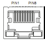
| Pin | Description |
| 8 | GND |
| 6 | A+ |
| 3 | B- |