
Open box to check
- If found any parts missing or found drives damaged, do not install them.
- The servo drive must be used with a matching servo motor.
Installation
- Installed on a non-flammable metal frame to prevent intrusion of dust, corrosive gases, conductive objects, liquids and flammable materials, and maintain good heat dissipation conditions;
- When installing, be sure to tighten the mounting screws of the drive. The servo drive and servo motor should be protected from vibration and must not be subjected to impact.
Wiring
- Please perform the wiring work by professional electrical engineers;
- Before wiring, please confirm that the input power is in the off state. Wiring and inspection must be performed after the power is cut off and the drive indicator is off to prevent electric shock;
- When plugging and unplugging the terminal of the drive, please make sure that the drive indicator is off;
- The grounding terminal PE must be reliably grounded through the left side of the drive;
- Please set the emergency stop circuit outside the controller;
- Do not connect the power input cable to the output U, V, W terminals;
- Tighten the output terminals with a suitable torque.
Power on
Please confirm whether the main circuit input power supply and the rated working voltage of the drive are consistent; Do not test the drive for high voltage and insulation performance;
Do not connect the electromagnetic contactor or electromagnetic switch to the output circuit.
General
DSL806 low voltage direct current servo drive is developed by high-performance processor, which provides users with a cost-effective servo control.
The solution is to ensure the stability and reliability of the system and to meet the most common application functions and performance.
Compared with stepping products, the servo drive has the advantage of low noise, low heating, high speed, constant torque output, no loss of step.
Compared with stepping servo products, this servo drive completely abandoned the inherent disadvantages of stepping products. Function, performance and reliability are better.
Compared with worldwide well known high-voltage servo, this drive has the similar performance with cheaper price and easy to use.
I. Basic Characteristics
- Working voltage: 18V-60VDC;
- Output current: rated 8A, peak 24A;
- Rated speed: 3000RPM, supporting the highest 10000RPM;
- Compatible motor: 5W-600W low voltage servo motor, DC brushless motor with encoder or hollow cup motor.
- Control mode: external pulse, analog, RS232 communication control. For position, speed and torque mode;
- Parameter adjustment: RS232 communication, PC debugging software written, or handheld debugger.
- Abnormal protection: with under-voltage, over-voltage, overload, over-current, encoder abnormal functions. Alarm output function inside.
II. Applicable fields
All kinds of electronic processing equipment, production line transmission equipment, medical equipment, instruments and meters, precision testing equipment, channel or gate control, AGV/RGV, Cartesian robot, servo length positioning, garage block control, and equipment, Feeding equipment, auxiliary motion equipment, grabbing and handling machinery, jet printers, photo machines, households and office automation devices.
III. Technical indicators
Using FOC field oriented control technology and SVPWM space vector modulation algorithm. The parameters for the motor can be easily modified to fit various specifications of the motor, built-in electronic gear, graphical debugging and monitoring software. Customization is available according to the user’s functional required. Simple control functions can be integrated.
- Repeat tracking error: ±1pulse;
- Speed control accuracy: ±1RPM;
- Receiving frequency range: 1MHZ;
- Maximum speed support: 10000RPM;
- Minimum speed support: 1RPM;
- Positioning accuracy support: 1/10000;
- Maximum no-load acceleration: 200RPM/ms;
- Suitable motor: 24V/36V/48V/60V low voltage servo motor, brushless DC motor with encoder or hollow Cup motor.
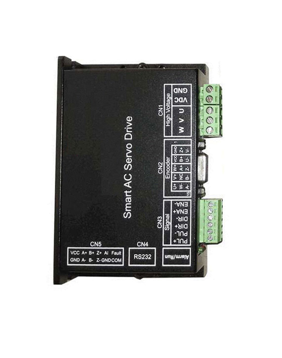
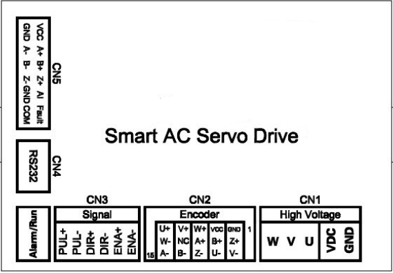
IV. Interface identification
4.1 Power Motor Connector CN1
| Item | Mark | Description | Note |
| 1 | VDC | Input Power + | DC 18V-60V |
| 2 | GND | Input Power – | |
| 3 | U | U phase | Must be connected to the motor as indicated |
| 4 | V | V phase | |
| 5 | W | W phase |
4.2 Encoder Connector CN2
| Item | Mark | Description | Item | Mark | Note |
| 1 | GND | Output Power Ground | 7 | B+ | Encoder B phase positive input |
| 2 | VCC | Output Power +5V | 8 | A+ | Encoder A phase positive input |
| 3 | W+ | Encoder W phase positive input | 13 | Z- | Encoder Z phase negative input |
| 4 | V+ | Encoder V phase positive input | 14 | B- | Encoder B phase negative input |
| 5 | U+ | Encoder U phase positive input | 15 | A- | Encoder A phase negative input |
| 6 | Z+ | Encoder Z phase positive input |
4.3 Control Connector CN3
| Item | Mark | Description | Note |
| 1 | PUL+ | Phase positive input | Pulse signal: pulse rising edge is effective. 4-5v at high level, 0-0.5v at low level, Pulse width should be greater than 1.6us, If you use 12V or 24V, you must connect 1.5-2.2K resistors in series. |
| 2 | PUL- | Phase negative input | |
| 3 | DIR+ | Direction positive input | Direction signal: input between DIR+ and DIR- Reverse at high level, and vice versa. The direction signal should be established at least 5us before the pulse signal. 4-5V at high level and 0-0.5V at low level. If you use 12V or 24V, you must connect 1.5-2.2K resistors in series. |
| 4 | DIR- | Direction negative input | |
| 5 | ENA+ | Enable positive input | Enable signal: This signal is used to enable or disable the servo motor. When the high level between ENA+ and ENA-, the drive will cut off the motor power, leaving the motor in a free state and not responding to the pulse. Enable the motor when the low level between ENA+ and ENA-, If you use 12V or 24V, you must connect 1.5-2.2K resistors in series. |
| 6 | ENA- | Enable negative input |
| Terminals No. | Description | Note |
| 2 | RXD | Connect to Computer serial port TXD |
| 5 | TXD | Connect to Computer serial port RXD |
| 6 | +5V | Drive external +5V output, maximum 100mA |
| 3 | GND | Signal ground |
| Item | Mark | Description | Note |
| 1 | VCC | Output power +5V | Drive external +5V output,maximum 100mA |
| 2 | GND | Output power ground | |
| 3 | A+ | Differential output A+ | Encoder feedback output, consistent with the encoder input line number |
| 4 | A- | Differential output A- | |
| 5 | B+ | Differential output B+ | |
| 6 | B- | Differential output B- | |
| 7 | Z+ | Differential output Z+ | |
| 8 | Z- | Differential output Z- | |
| 9 | AI | Analog input | 0-5V,0-2.5 REV,2.5-5V FWD |
| 10 | GND | Output power ground | |
| 11 | Fault | Open set alarm output | Above 5V, it needs to be connected in series with 2K resistors. |
| 12 | COM | Open set output common port | Connect controller common port |
V: Control Mode
5.1 Basic control
This drive provides three basic operating modes: position, speed and torque. Using a single control mode, all operating modes and instructions are listed below.
| Control mode selection | Control source selection | Note |
| Position control mode | External pulse input | The drive accepts a position command to control the motor to the target position. The position command is input by the terminal, and the signal type is pulse + direction |
| PC digital input | Relative position: The drive enable start time is mechanical zero point, each time the PC digital value inputted, the motor rotates the target distance.
Absolute position: The drive enable start time is mechanical zero point, each time the PC digital value inputted, the motor is referenced to the mechanical zero point and is rotated to the target position. | |
| External analog input | When the external analog input is 0~+5V, the motor rotates in absolute position mode -16384~+16384 pulses | |
| Speed control mode | PC digital input | Input range:-10000RPM~+10000RPM |
| External analog input | When the external analog input is 0~+5V, the motor runs at -12000RPM~+12000RPM. | |
| Torque control mode | PC digital input | The input range is -7500~+7500. The corresponding output current is 24A. When the input is positive va;ie, it corresponds to the positive torque, the negative value corresponds to the reverse torque. |
| External analog input | When the external analog input is 0~+5V, the corresponding digital torque range is: -16384~+16384. Drive internal limit to a maximum of 7500 |
5.2 Communication Control
In addition to the basic control methods described above, the drive also provides RS232 communication control. When selecting the communication control mode, whether you select any of the control modes, the control source must select the PC digital input, then transmit data according to the communication format and drive. The following are some specific instructions for communication control.
| Function | Data address(A1) | Data up 8 bits (A2) | Data low 8 bits (A3) | Data checksum (A1+A2+A3) | Note | |
| Motor start | 0x00 | 0x00 | 0x01 | 0x01 | Write motor enable | |
| Motor stop | 0x00 | 0x00 | 0x00 | 0x00 | Write motor disable | |
Speed mode selection —PC digital input | 0x02 | 0x00 | 0xc4 | 0xc6 | Control mode given command source selection | |
Position mode selection — External pulse input | 0x02 | 0x00 | 0xc0 | 0xc2 | Control mode given command source selection | |
| Position mode selection –PC digital input | 0x02 | 0x00 | 0xd0 | 0xd2 | Control mode given command source selection | |
| Speed proportional gain | 0x40 | Take low 8 bits (A1+A2+A3) | It is recommended to make the changes based on the factory default parameters according to the actual situation. | |||
| Speed integral gain | 0x41 | Take low 8 bits (A1+A2+A3) | ||||
| Speed differential gain | 0x42 | Take low 8 bits (A1+A2+A3) | ||||
| Position proportional gain | 0x1a | Take low 8 bits (A1+A2+A3) | ||||
| Position differential gain | 0x1b | Take low 8 bits (A1+A2+A3) | ||||
| Position feed forward gain | 0x1c | Take low 8 bits (A1+A2+A3) | ||||
| Speed mode (available when PC digital input)– acceleration and deceleration speed setting | 0x0a | acceleration | deceleration | Take low 8 bits (A1+A2+A3) | Actual speed=( acceleration and deceleration speed/250)*6000 | |
| Speed mode –PC digital input — speed given | 0x06 | Take low 8 bits (A1+A2+A3) | Set digital 16384 corresponding to the actual speed 6000RPM | |||
Position debugging mode The position is given a up 16 bit –PC– position | 0x50 | Take low 8 bits (A1+A2+A3) | Up 16 bits of the 32-bit data input | |||
Position debugging mode The position is given a low 16 bit –PC– position | 0x05 | Take low 8 bits (A1+A2+A3) | Low 16 bits of 32-bit data input | |||
| Find Z signal, mechanical origin | 0x53 | 0x00 | 0x00 | 0x53 | ||
| Absolute position/relative position switch control in position mode | 0x52 | 0x00 | 0x00 | 0x52 | Absolute position | |
| 0x52 | 0x00 | 0x01 | 0x53 | Relative position | ||
Speed limit value in position mode (The actual speed at the given position under the position command) | 0x1d | Take low 8 bits (A1+A2+A3) | Set digital 16384 corresponding to the actual speed 6000RPM | |||
| Speed limit value in position mode: In the position mode PC input acceleration/deceleration setting parameter, “Acceleration/Deceleration” set to maximum will be the leading role, otherwise it will affect the final speed limit value. For example, in the host computer debugging software, input “Acceleration: 255 / Deceleration: 255” in the position mode PC input acceleration/deceleration setting, then submit the input. After the input is completed, the final speed value for the limit is the value assigned to the address of register 0x1d. | ||||||
| Read monitoring parameters | Sending 0x80 0x00 0x80 directly, drive will return the corresponding monitoring information | ||||||
| Failure state | 0x80 | 0x00 | Status_word | Take low 8 bits (A1+A2+A3) | Status_word is customized parameters | ||
The fault information corresponding to each bit of Status_word is as follows (highly effective) : Status_ov_i = Status_word^1; over current Status_ov_u = Status_word^2; over voltage Status_err_enc = Status_word^3; encoder error Status_ov_q = Status_word^5; under voltage Status_ov_load = Status_word^6; over load | |||||||
| Busbar voltage | 0xe1 | Take low 8 bit (A1+A2+A3) | (Deviation 2V) | ||||
| Output current | 0xe2 | Take low 8 bit (A1+A2+A3) | The actual current will reduced by 100 times | ||||
| Output speed | 0xe4 | Take low 8 bit (A1+A2+A3) | Returned digital 16384 corresponding to the actual speed 6000RPM | ||||
| Position give up 16 bits | 0xe6 | Take low 8 bit (A1+A2+A3) | If the position is given as 32-bit data, the actual value is recombined according to the up 16 bits and the low 16 bits. | ||||
| Position give low 16 bits | 0xe7 | Take low 8 bit (A1+A2+A3) | |||||
Position feedback up 16 bits | 0xe8 | Take low 8 bit (A1+A2+A3) | If the position feedback is 32-bit data, the actual value is recombined according to the up 16 bits and the low 16 bits. | ||||
| Position feedback low 16 bits | 0xe9 | Take low 8 bit (A1+A2+A3) | |||||
Detailed description of the communication control instructions:
(1) The data command format received by the controller is: address + data up 8 bits + data low 8 bits + data checksum
(take the low 8 bits value of the summary of first three data) If the host computer sends correctly in this format, the drive will immediately return the two addresses of the command to the host computer, which indicates that the drive has successfully received the command. For example: the host computer sends: 0x09 0x32 0x32 0x6d, the drive returns to the host: 0x09 0x09, at this point, it means the drive has been finished receiving. (Note: There must be more than 1ms delay between each data instruction, otherwise the data is prone to error).
(2) When the position debug mode is selected and the host machine sends the control command through the serial port, the setting sequence is: set the drive to position debugging mode (send 0x02 0x00 0xd0 0xd2) set the speed limit value in position mode motor start (0x00 0x00 0x01 0x01) position given up 16 bits The position is given by the low 16 bits. If the position debug mode has been determined and the motor has been started, it will not need to be sent repeatedly when it is sent next time.
(3) If all parameters have been set when the drive is debugging parameters, such as acceleration and deceleration, control mode, speed limit (the factory has set a suitable value). At this time, it is only necessary to set the motor to start, and then send the position. Step: Motor start (0x00 0x00 0x01 0x01) position is given up 16 bits position is given low 16 bits.
(4) The input length given by the position is a 32-bit data, which must be decomposed to a up 16 bits and a low 16 bits when transmitted.
Moreover, the 16-bit data is also need to be decomposed into up 8 bits and low 8 bits. The data splitting will be done by the data format generator in the file. The user only needs to input the data to be sent, it can be automatically split into the format used for communication.
(5) Use of the data format generator. For example, set the acceleration and deceleration to 50 and place it in the 16-bit data generation box: Address: 09 Acceleration input 50, Deceleration input 50 then display. At this time, the data format is generated 0x09 0x32 0x32 0x6d and then the host computer can send this command to set the acceleration and deceleration in the position debugging mode.
(6) Set the 32-bit position reference command. The 32-bit data corresponds to the number of pulses. For example, when the numerator value and denominator value are both set to 1 in the electronic gear, and the encoder lines is 2500, the number of pulses required per one revolution of the motor is 10000.
When the position reference is written as 10000, the drive starts at the mechanical zero point and the motor rotates once. When 100000 is written, the motor rotates 10 revolutions. If 0 is written again, the motor rotates to the position just when starting.
(7) Regarding the position mode, whether the transmission position command is an absolute position or a relative position. When the send command is 0X52 0X00 0X00 0X52, the send position is the absolute position. When the send command is 0X52 0X00 0X01 0X53, the position is the relative position.
(8) In position mode, the maximum stable speed limit of the motor output is determined by VLimit (provided that the acceleration/deceleration in position mode has been set to a maximum value of 255). The send command is (0x1d set value up 8 bits set value low 8 bit checksum) where the set value corresponds to the limit speed = (requires set limit speed / 6000) * 16384 , the obtained data is rounded off. For example, if the motor requires 3000 RPM, the set value is 8192. If 1RPM is required, the set value is 3 (rounded).
(9) About the problem of finding the origin of the mechanical Z signal, after the parameter configuration is completed, after sending the origin operation (0x53 0x00 0x00 0x53). And after sending the motor start (0x00 0x00 0x01 0x01), the motor will rotate slowly until the Z signal origin is found, and then it will not move.
(10) About monitoring commands. Send the monitoring command is (0x80 0x00 0x80), after receiving the command, the drive returns the following data: fault information, busbar voltage, output current (which has been amplified by 100 times, the actual display current needs to be divided by 100. For example, the received value is 123. It means the current is 1.23A), output speed (output speed is digital, the conversion relationship is: actual speed = (digital speed / 16384) * 6000), the current position given value up 16 bit, the current position given value low 16 bits, the current position feedback value up 16 bits, and the current position feedback value low 16 bits. Please refer to the above table for the corresponding relationship. The format returned is four data per frame.
The format is: Address Data up 8 bits Data low 8 bits Checksum (takes the low 8 bits).
VI. The use of the host computer debugging software
The drive provides easy-to-use debugging software, all parameters can be written to the inside of the drive through the debug software, while monitoring the status of the drive. The following details will show the use of the software.
6.1 Serial Port Operation
After opening the software, there is a serial port setting in the file drop-down list. Select the serial port number of the PC, and the other ones are as default like the picture below. After setting, apply the settings and open the serial port. The first time the software is opened, the parameters of the drive are read out by default. If the user needs to load the parameters that have been stored and modified, the stored parameter file can be opened from the software.
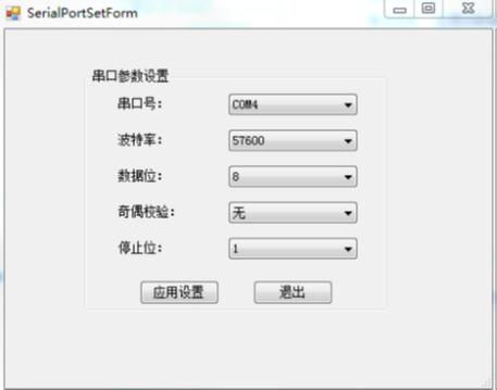
Figure 6-1
6.2 Basic parameter settings
Pulse direction reference selection (this option is only valid when the position mode external pulse input):
When forward rotation is selected, the input signal is:
pulse + direction (high level), at this time the drive is rotating forward.
pulse + direction (low level), at this time the the drive is rotating reversed.
When reverse is selected, the input signal is:
pulse + direction (low level), at this time the drive is rotating forward.
pulse + direction (high level), at this time the drive is rotating reversed.
Overload factor: The setting parameter range is 0~300%, the default is 200%. This setting is the maximum current allowed to output of the drive. If exceeded the set overload time, it will stop and alarm.
Analog dead zone: The approved range of mechanical zero, zero speed, and zero torque when using analog control. For example, when set to 50, when the digital quantity sampled by AD is less than 50, the drive forced sample value will be 0.
Electronic gear: actual position command = input pulse command * (numerator of the electronic gear ratio / denominator of the electronic gear ratio).
The specific settings are shown in Figure 6-2-1, 6-2-2.
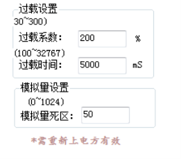
Figure 6-2-1
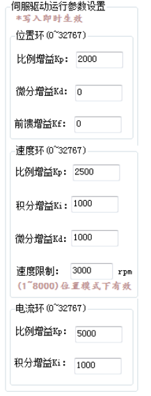
Figure 6-2-2
6.3 Drive PI Parameter Settings
The parameters that the drive is now open are position loop PDF, speed loop PID. There is a great relationship between parameter adjustment and response. The actual working environment is subject to adjustment.
Under the default parameter setting, if the motor vibrates, reduce the value of the speed loop KpV and increase the value of the speed loop KI appropriately after vibrating situation. If the speed loop KpV is reduced, however the motor is still vibrated, and then reduce the KpP value of the position loop.
In the case of none vibration, slowly increase the KpV value of the speed loop while reducing the KiV value of the speed loop. Under the condition of rigid demand, appropriately increasing the value of the speed loop KdV can reduce the vibration of the motor, and increasing the excessive KdV will cause high-frequency noise, please pay attention, If the above cannot reduce the vibration, properly reduce the KpI value of the current loop. The PI parameter of the current loop is now encrypted. For modification, please contact the factory.
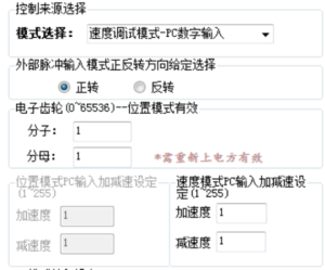
Figure 6-3
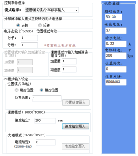
Figure 6-4 / Figure 6-5
6.4 Mode Selection and PC Reference
The drive provides 7 control source options, users can select different control methods according to different needs. In the corresponding mode of PC digital input, the text area of the three modes is valid, but the acceleration and deceleration settings are valid only in the PC input mode.
6.5 Status Monitoring
The host computer software provides real-time monitoring of the bus voltage, output current, motor speed, position reference, and position feedback information. The specific status monitoring is shown in Figure 6-5.
6.6 Simple Oscilloscope
The debugging software provides periodic monitoring of U-phase digital current, V-phase digital current, current reference, current feedback, speed reference, speed feedback, position reference, and position feedback signal. At the same time, the current sample waveform or the load history waveform can be recorded
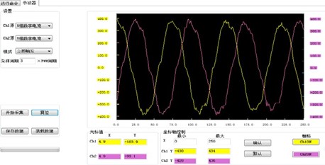
Figure 6-6
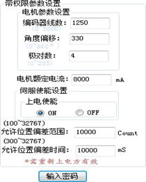
Figure 6-7 Password: 8888
6.7 Setting of motor parameters
The motor parameters are fixed when the drive leaves the factory with the motor, and the user can not change them at will, otherwise the drive and equipment will be damaged.
Note: if you want to replace the motor, please confirm the parameters with the motor provider and drive manufacturer and write the relevant setting again .Motor related parameters are non-modifiable parameters after the drive is energized. After modification, it will be valid only after re-energized or the drive system reset.
Number of encoder lines: the resolution of the encoder corresponding to the motor nameplate;
Angle offset: the Angle offset value of the encoder Z signal corresponding to the motor U opposite to the electromotive force negative over zero;
Number of pole pairs: motor pole pairs.
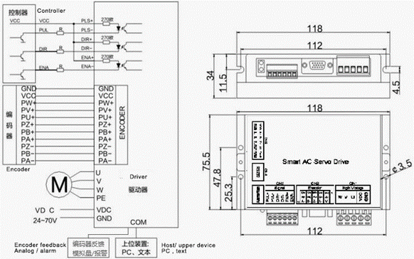
VII. Typical wiring of control signals
Figure 7-1 Wiring diagram of differential mode control signal interface
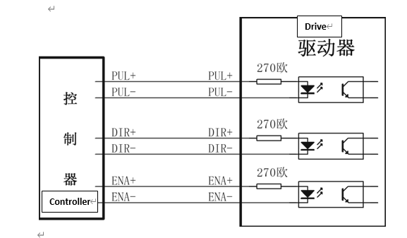
Figure 7-2 Single-ended mode control signal interface wiring diagram
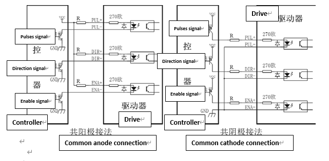
Special reminder: When the control signal is 12V or 24V, an external current limiting resistor is required. 12V is connected to 1K resistor and 24V is connected to 2K resistor. Otherwise, long-term operation will damage the drive’s opto-isolated device.