Brief Introduction
- Surface mounted technology to improve the reliability of the circuit.
- Incredible small dimension with high voltage.
- AC and DC dual voltage support.
- We present industrial chips to meet industrial application temperature requirements.
- Optoelectronic isolation for analog voltage / PWM pulse / pulse frequency signal and other security interfaces.
- Super reliable design with safe foreward and reverse, safe start, anti-interference, over temperature / over current / short circuit / under voltage / over voltage and other protections.
Definition of Part number
| BLSD | 220 | 06 | ADC | 2Q | SH | 8 | 030 | 0.5 | T | A | P | C | K | F |
|---|---|---|---|---|---|---|---|---|---|---|---|---|---|---|
| BLDC drive | Rated Voltage | Peak current limit | AC/DC input ① | Control mode | Parameter ② | Pole | Max speed range ③ | SV ramp RC time | Temp ④ | Sensor type ⑤ | Speed regulation type ⑥ | Loop type ⑦ | Loop control ⑧ | PG type ⑨ |
- ① AC/DC input: This code shows the DC Power input type of the drive: ADC = AC and DC dual purpose; DC = Normal DC input; LDC = Ultra low voltage DC input; WDC = Wide range DC input; AC = AC input.
- ② Parameter: This code shows the parameter type of the drive: S = Simple fixed parameter; N = Variable parameter; H = High current; SH = Small type high voltage; HV = High voltage.
- ③ Max speed range: This code shows the max speed range of the drive, the unit is rpm/100.
- ④ Temp: This code shows the temperature range of the drive: T = -40 ~ +65 ℃ , None = -10 ~ +45℃ .
- ⑤ Sensor type: This code shows the hall sensor degree of the drive: A = 60° Hall sensor, None = 120° Hall sensor.
- ⑥ Speed regulation type: This code shows the speed regulation type: P = 0-3KHz speed regulation, None = 0-10V voltage or PWM speed regulation.
- ⑦ Loop type: This colde shows the loop type: C = Electric current loop, None = Speed loop.
- ⑧ Loop control: This code shows the open loop control or close loop control: K = Open loop control, None = Close loop control.
- ⑨ PG type: This code shows the PG type: F = PG synchronize to one phase hall signal, None= 6 times frequency multiplier of hall signal.
Note: In order to let the part number easier to read, Some part number code will not be shown in the specification table, a code “X” will be instead. The full part number will be provided in the quotation or the proforma invoice…
Specifications
| Model | Temperature range (ºC) | Voltage range (VDC/VAC) | Peak Current (A) | Continuous Current (A) | 60º/120º Hall sensor | PWM f(kHz) | PI Close loop of speed or current | RC Ramp time (S) | Reference Input Range | LV /OV Alarm | Alarm diag output | PG speed pulse output | SC /OT | Safe F/R | Safe Start |
|---|---|---|---|---|---|---|---|---|---|---|---|---|---|---|---|
| BLSD11001ADC-2Q-SH-X | -10~+45 or -40~+65 | AC 110 (AC 45-140) or DC 155 (DC 60-195) | 1 | 0.5 | ★ | 16 | ★ | ★ | 0-10V or PWM or 0-3KHz pulse customizable | √ | √ | 4p@8-pole or 24p@8-pole customizable | √ | √ | √ |
| BLSD11002ADC-2Q-SH-X | 2 | 1 | 16 | ||||||||||||
| BLSD11004ADC-2Q-SH-X | 4 | 2 | 16 | ||||||||||||
| BLSD11006ADC-2Q-SH-X | 6 | 3 | 16 | ||||||||||||
| BLSD22001ADC-2Q-SH-X | AC 220 (AC 45-275) or DC 310 (DC 60-385) | 1 | 0.5 | 16 | |||||||||||
| BLSD22002ADC-2Q-SH-X | 2 | 1 | 16 | ||||||||||||
| BLSD22004ADC-2Q-SH-X | 4 | 2 | 16 | ||||||||||||
| BLSD22006ADC-2Q-SH-X | 6 | 3 | 16 |
- ★ in the table means “Customizable”
- All the drivers in the above table can use AC and also DC input. When use AC, the driving voltage mode in the motor port is DC, the voltage is 1.4 times than input AC voltage. When use DC, the driving voltage mode in the motor port is DC, the voltage is same with input DC voltage
In-Depth Applications for this Small High Voltage BLDC Motor Driver
The BLSD-SH Series is designed for machinery where space is at a premium, but high voltage AC power is required. Its “SH” (Small type High voltage) designation makes it a unique solution for integrating a powerful small high voltage BLDC motor driver into tight enclosures. Key application areas include:
- Industrial Machinery: Ideal for construction spraying machines, PCB board cutting machines, and textile equipment that require a compact, high-power small high voltage BLDC motor driver.
- Automation & Robotics: This BLDC motor controller can be embedded directly into robotic arms or automated assembly stations, saving cabinet space while driving powerful motors.
- Specialized Equipment: Operates engraving machines and other precision tools that require a small high voltage BLDC motor driver that can run on 220V AC power.
Control Interface and Features
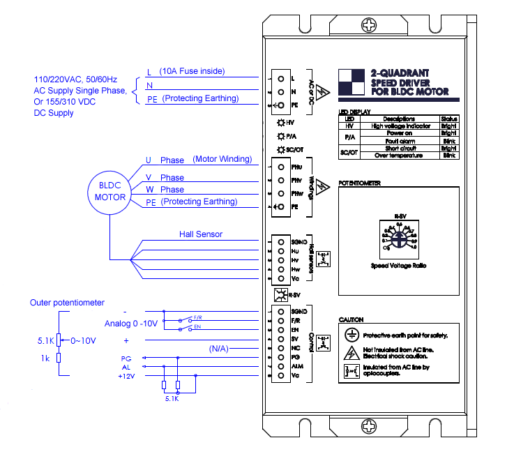
1. Power Supply Port:
This driver can be used for wide range voltage both in DC or AC. For AC supply the voltage is 45~140/45~275V, 50-60Hz AC single phase. For DC supply, the voltage is 60~200/60~385V. L, N does not distinguish the +/-polar and can be connect randomly. Please take attention to the high voltage warning.
2. Motor Windings Port:
Connect three phases of windings to the U/V/W points in correct sequence. PE on motor case must be connected to PE point of this port for safety. Please take attention to the high voltage warning.
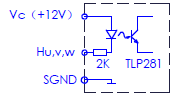
3. Motor Hall Sensor Port:
Connect Hall sensors Hu/Hv/Hw to the port in correct sequence. This port is insulated from inside circuit by optocoupler and power Vc supply is provided by driver.

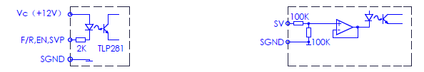
4. Control Signal Port:
This port is insulated from inside circuit by optocoupler and one line isolated 12V power supply is provided by driver for external use, the current is less than 50mA.
- F/R: Rotating direction control. The driver can provide safety forward/reverse control.
If the direction is changed suddenly when the motor is running, the motor will cut down the power and sliding to zero speed smoothly and then change rotating direction in order to avoid the shock impact. At the moment that the driver power up, if the speed is not zero, then it will start until the speed is zero. - EN: Enable control function. Enable when optocoupler conduct. The driver can only be work when enable. The alarm can be reset by EN=disable once

- SV: Speed control instruction input. Analog reference voltage input of 0~10V. Input impedance 200K. It is insulated from inside circuit by a optocoupler. Also can input amplitude 10V, frequency 50-100Hz PWM instruction. When F-V converter inside, it can input amplitude 10V, frequency 0-3KHz pulse to do the speed control.
- NC: The port is unavailable.
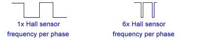
- PG: Speed pulse output in OC(30Vmax/5mA). This signal can be made in synchronize to one phase hall sensor signal or 6 times frequency multiplier. The motor speed is in proportion to the frequency. Motor speed(rpm)=PG frequency(Hz)x120/N. N is the pole number of motor. Or, motor speed(rpm)=PG frequency(Hz)x120/N/6 (6 times frequency multiplier).

- AL: Alarm output in OC(30Vmax/5mA). The driver has self-diagnostic function. When the following conditions come, the alarm comes up, and optocoupler will conduct.
For items of NO.1~6, green LED P/A will be blinking. The alarm can be reset by EN=disable once.
For items of NO.7, red LED will brighten. The alarm can be reset only you Off-on supply again.
1. Incorrect Hall signal 2. Low control voltage 3. OT at main chip 4. LV or OV at power supply voltage 5. current continuous overload (Peak current limiting) over 6 seconds 6. Case temperature over (red alarm LED blinking) 7. Short circuit in motor windings.

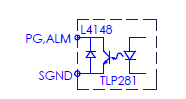
Vc,SGND:One line isolated 12V power supply is provided by driver for external use, the current is less than 50mA.
5. LED Display:
- HV: DC bus voltage instruction LED. Green color LED. High voltage on DC power line when brighten. Warning: Do not open the case and touch the high voltage parts when this LED brightens.
- P/A: Green color LED. Control supply and Alarm. LED will be blinking in alarm state.
- SC/OT: Short circuit/over temperature indicator LED. Red color LED. When short circuit in windings of motor, the LED will be brighten. The alarm can be reset only you Off-on supply again after removal of fault. When over temperature at driver case the LED will be blinking. The alarm can be reset by EN after apply the cooling measures.
6. Potentiometers:
R-SV: Reference ratio, 0-100%. Usually used for precisely calibrating in full speed control instructions. Also can be used for internal speed control potentiometer by its attenuation effect.
Outline


Customization
![]() | ![]() | ![]() |
| Heat sink | Motor tuning | Logo / brandmark |
| Item | Description |
|---|---|
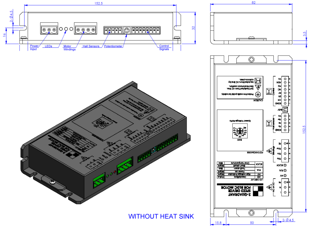
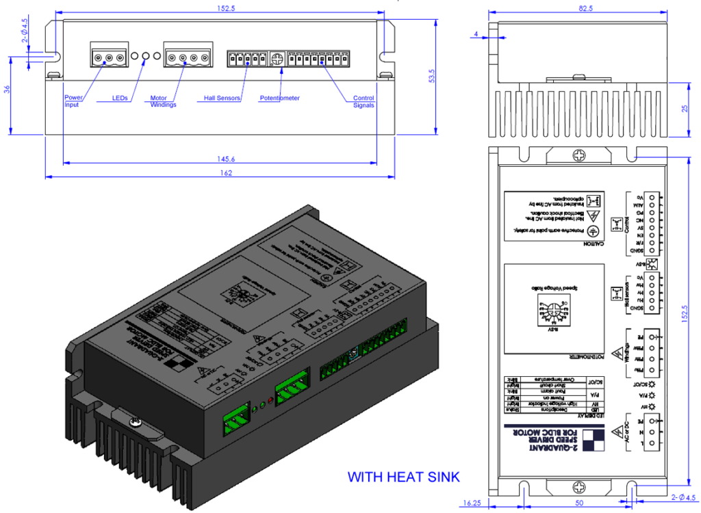
| Heat Sink | Optional heat sinks can be installed upon request to enhance thermal performance. |
| Motor Tuning | We provide driver tuning services to optimize performance with motors of different pole counts, ensuring a perfect match for your application. |
| Logo & Brandmark | We offer OEM/ODM services, including printing your company logo or brandmark directly onto the driver’s frame. |
Frequently Asked Questions (FAQ)
Q: What is the main benefit of the “Small High Voltage” (SH-Series)?
A: The “SH-Series” is a small high voltage BLDC motor driver that combines two key features: a compact, small-size footprint and an AC/DC dual-purpose input (up to 275VAC). This allows you to run high-power motors directly from an AC outlet without needing a large external power supply or a large driver enclosure.
Q: What does “PI Closed-Loop” control mean for this driver?
A: This small high voltage BLDC motor driver uses a PI (Proportional-Integral) algorithm for its speed or current control. It reads the Hall sensor feedback (PG output) and compares it to the set speed (SV), then automatically adjusts the power to maintain that speed, even if the load changes.
Q: How do I control the speed of this BLDC motor controller?
A: This BLSD-SH small high voltage BLDC motor driver is highly flexible. You can control the speed using a 0-10V analog signal (at SV), a PWM pulse signal, or a 0-3KHz pulse frequency signal (at SVP), selectable via DIP switch.
Q: What safety features does this bldc motor drive include?
A: This small high voltage BLDC motor driver is built for safety. It includes reliable protections for incorrect Hall signals, low/over voltage (LV/OV), over-temperature (OT), over-load (OL), and short-circuit (SC), with alarm (AL) and LED indicators for diagnostics.
Q: Is this a full BLDC motor controller or just a driver?
A: This unit is a complete small high voltage BLDC motor driver and controller. It includes both the logic (controller) and the power stage (driver) in one compact package, ready to connect to your motor and control signals.


